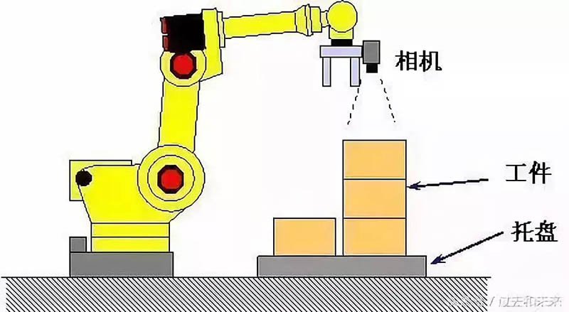
1. iRVision 2.5D visual stacking
The visual stacking program estimates the height of the target and guides the robot's motion to compensate for the offset of the target by adjusting the proportion of the target in the camera's field of view. This includes not only the rotation of the X-axis, Y-axis, and X-Y plane R, but also the Z-axis. The use of iRVision 2.5D allows robots to pick up targets for stacking piles using only a regular 2D camera.
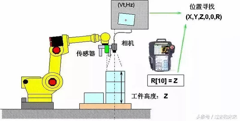
2. iRVision visual stacking program_1 (extracting Z-axis offset from register R)
This function uses visual calculation to find the 2D position of the target and the specified register value, and guides the robot's motion to compensate for the offset of the target, including not only the X-axis, Y-axis, and X-Y plane rotation degree R, but also the Z-axis.
Register R is used to store known target Z-axis height or Z-axis height information detected by distance sensors.
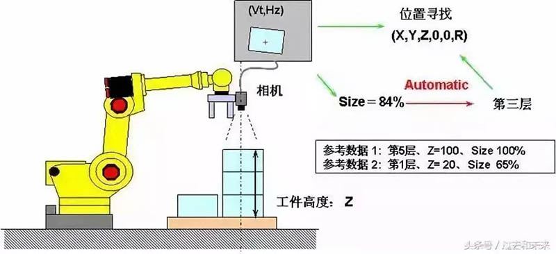
3. iRVision Visual Stacking Program_2 (Extracting Z-axis offset from stacking layers)
This function calculates the position of the target by combining visual detection results with the number of target layers (target height) determined based on the target proportion. The number of target layers is automatically determined based on the reference scale and height data, so even if there are slight scale errors in visual detection, the specific position of the target can be calculated through a discrete number of layers (target height).
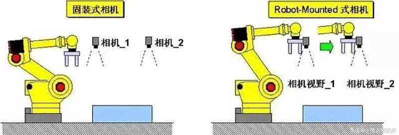
4. iRVision 2DV complex field of view function
The 2D complex field of view program provides the ability to locate large targets through several fixed cameras, which is equally effective for detection through Robot Mounted cameras.
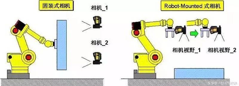
5. iRVision 3DL complex field of view function
The 3D complex field of view program provides the ability to locate large targets through several fixed 3D cameras, which is equally effective for detection through Robot Mounted cameras.
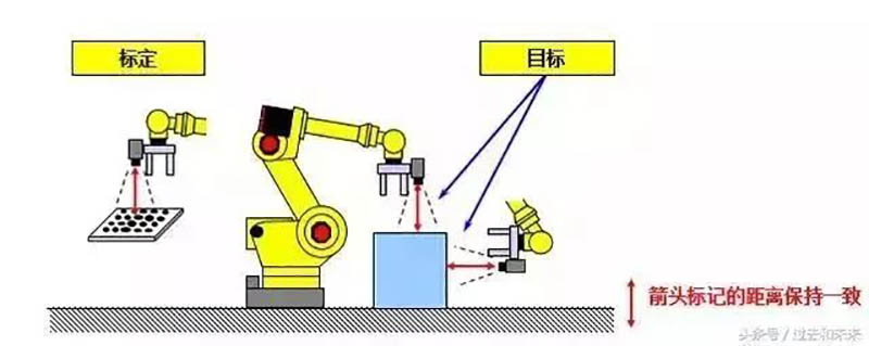
6. iRVision Floating Frame Function
The calibration of Robot mounted cameras can be used for iRVision programs at any position and direction as shown in the following figure. The motion compensation in 2D state is related to the actual position of the camera. Camera calibration can be performed at any position. Reduce teaching workload.
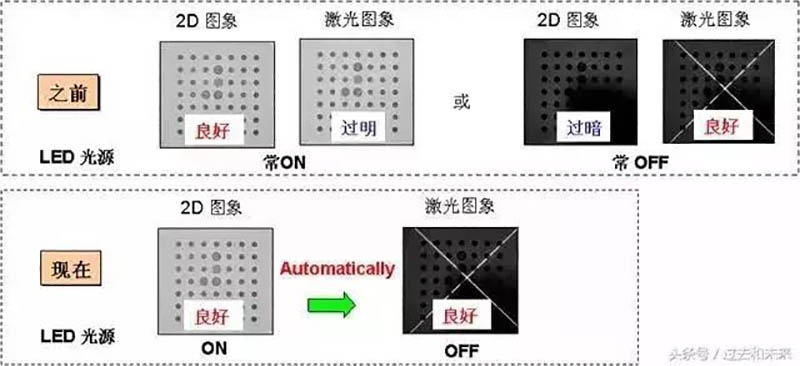
7. iRVision 3DL LED light source control
This feature supports synchronous control of LED light source ON/OFF when capturing 2D images and laser irradiation images in 3DL visual programs. Through this function, an appropriate external lighting environment can be obtained to enhance the overall visual system's capabilities.
8. iRVision automatic exposure function
Based on the changes in ambient light intensity, iRVision will automatically adjust the exposure time to achieve imaging effects similar to teaching good images, which may run around the clock.

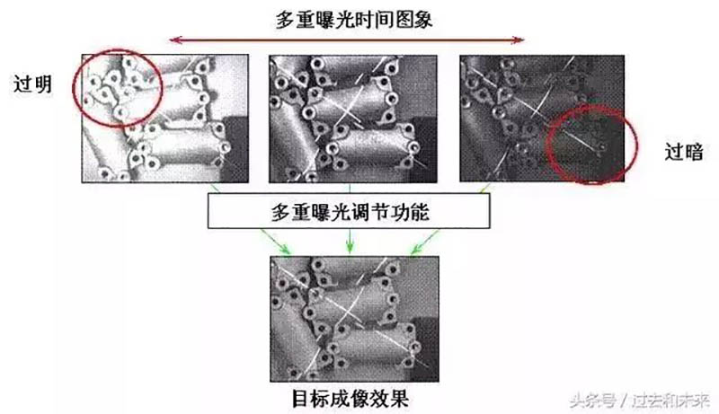
9. iRVision multi exposure function
By imaging with multiple different exposure times, select an image that is close to the teaching effect to achieve a wide and dynamic exposure range and imaging effect. This feature will have a good effect when the ambient light changes strongly.
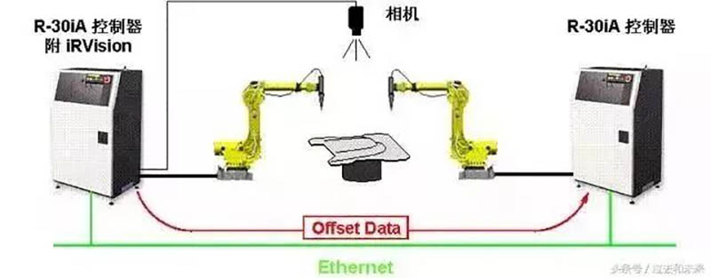
10. iRVision Ring Network Function (Robot Ring)
Through this feature, robots without an iRVision vision system can access the offset detection data of robots with an iRVision vision system through the network.
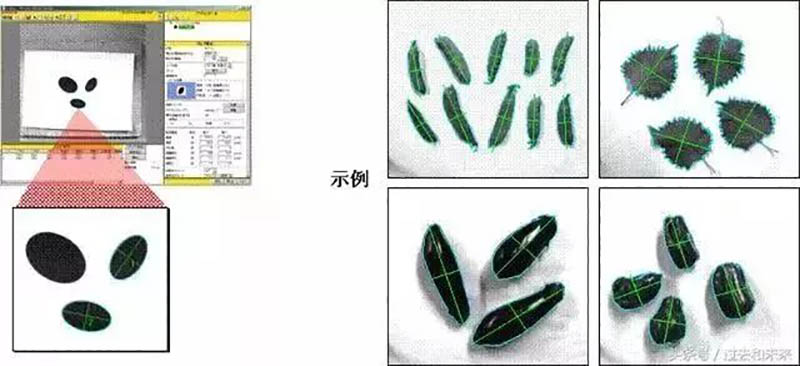
11. iRVision spot detection function (Blob Locator Tool)
Detect binary (black and white) target positions within the imaging range that have similar characteristics (such as perimeter, curvature, etc.) to the teaching model. Used in conjunction with conditional execution tool, it can be applied in various scenarios such as target alignment and quality detection.
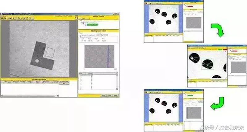
12. iRVision grayscale detection function (Histogram Tool)
Detect light intensity (imaging grayscale) within a specified area and calculate various characteristics such as average, maximum, minimum, etc. When used together with conditional execution tool, it can correspond to various scenarios such as target arrangement and target in place detection.
This function is equivalent to the Associate tool in V-500iA/2DV.
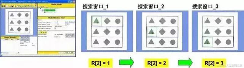
13. iRVision multi window detection function (Multi Window Tool)
Switch the corresponding preset search window by changing the value of register R in the robot controller.
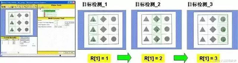
14. iRVision Multi Object Detection Function (Multi Locator Tool)
Switch the corresponding preset target visual program by changing the value of register R in the robot controller.
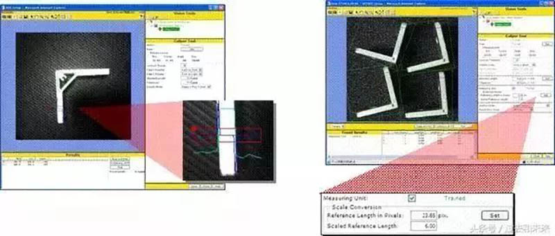
15. iRVision length measurement function (Caliper Tool)
Corresponding to the specified area, detect the target edge and measure the length (in pixel) between the two edges. Multiply by the conversion factor to convert to mm. It can correspond to application scenarios such as target arrangement and quality detection.
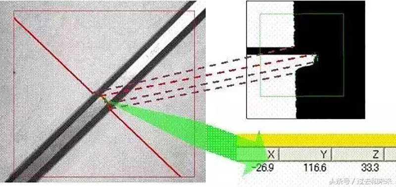
16. iRVision Cross Section Detection Function
Detect the local 3D characteristics of the target and display the cross-sectional shape of the target along the laser diffraction path. It is more effective when accurate positioning cannot be achieved in 3D vision programs due to the lack of effective feature quantities in 2D imaging.
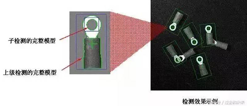
17. iRVision sub detection function (Child Tool)
Allow adding a sub object detection (GPM locator tool) under a parent object detection (GPM locator tool) to form a secondary detection directory. The sub detection will make dynamic judgments based on the results of the parent detection. When used together with conditional execution tool, it can correspond to various scenarios such as target arrangement and target in place detection.
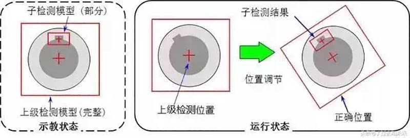
18. iRVision Position Adjustment Tool
Based on the results of sub detection, adjust the positioning position of the parent detection according to the obvious features of the target surface (such as holes and keyways) to obtain more accurate offset and rotation data. It is more effective for applications that cannot use the entire teaching model for directional positioning. For a superior detection, multiple subordinate sub detections can be used to analyze multiple local characteristics of the target.
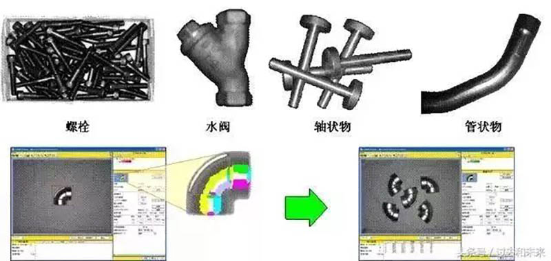
19. iRVision Surface Matching Tool (Curved Surface Matching Tool)
Detect the offset and rotation of surface targets through the stepped light intensity distribution on the target surface (bright or dark, displayed in different colors within the model). Identifying fully circular objects is possible.
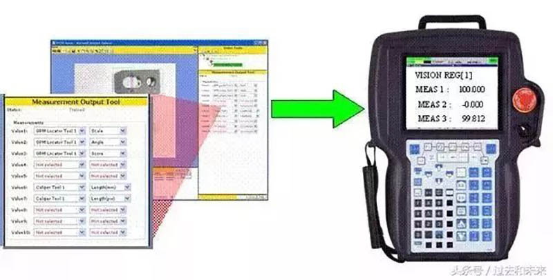
20. iRVision Measurement Output Tool
Output measurement values (Score/Score, Size/Scale in Locator tool, Length/Length in Caliper tool, etc.) to the visual register VR. These data can be copied to the robot data register R and freely called in the TP program.
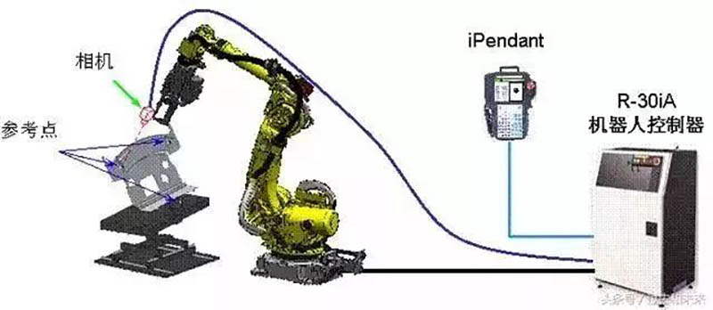
21. iRVision Visual Replacement Function (Vision Shift)
By adjusting the robot TP program through visual programming to correspond to the actual workpiece position, simply add a camera to the robot gripper end to perform this function. The position data of any three reference points on the fixed workpiece will be automatically detected and compensation data will be calculated.
After offline programming or relocation of the robot system, using this feature can greatly reduce the time for the robot to re teach.
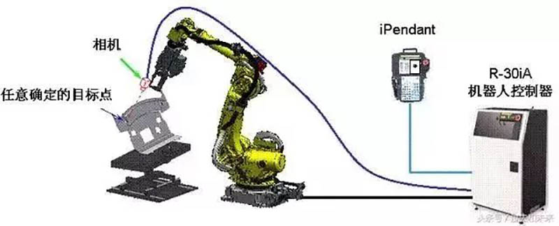
22. iRVision Vision Mastering
By using a visual program to compensate for the zero position data of the robot's J2~J5 axes, this function can be performed by simply adding a camera to the robot's gripper end. The robot changes different poses, and the relative position data between the camera and the determined target point will be automatically detected and compensation data will be calculated.
This feature can be applied to improve the accuracy of robot TCP teaching, Vision shift offline programming, and other visual applications.
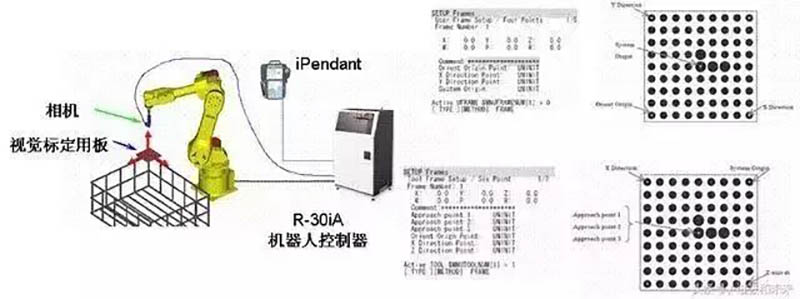
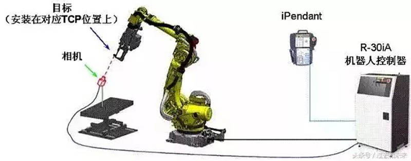
23. iRVision Visual Coordinate System Setting_1 (Vision Frame Set)
By setting the robot TCP through a visual program, simply add a camera at the corresponding position of the robot's gripper TCP to perform this function. The robot transforms different poses, and based on the relative position data between the camera and the target point in the corresponding user coordinate system, the robot's corresponding TCP will be automatically detected and calculated. This feature can improve the speed and accuracy of TCP teaching.
24. iRVision Visual Coordinate System Setting Function_2 (Vision Frame Set)
Another function of coordinate system setting is to visually set a user coordinate system that is equivalent to the visual calibration board. By installing a camera at the end of the robot claw, the user coordinate system UF is set at the origin position of the visual calibration board (four point method), or when the visual calibration board is installed at the end of the robot claw, the tool coordinate system UT is set at the origin position of the visual calibration board (six point method).