The advantages of structured light vision:
Non contact, large amount of information, high measurement accuracy, and strong anti-interference ability.
The calibration of structured light visual sensor parameters includes camera parameter calibration and structured light plane parameter calibration.
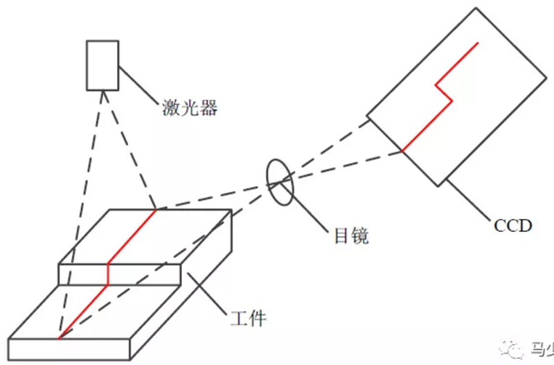
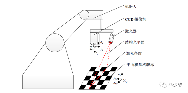
Schematic diagram of structured light visual measurement
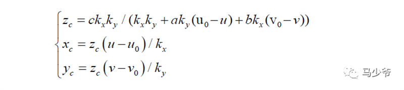
We do not consider lens distortion and simplify the camera imaging model to a small hole imaging model. The relationship between the image coordinates Pf of feature points and their three-dimensional coordinates P in the camera coordinate system can be expressed as:
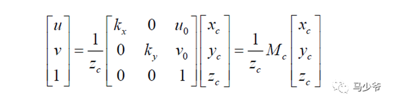
Among them: (u, v) is the image coordinate of the feature point, (u0, v0) is the image coordinate of the optical axis center, (kx ky) is the amplification factor in the X-axis and Y-axis directions, (xc yc zc) is the coordinate of the feature point in the camera coordinate system, and Mc is the internal parameter matrix of the camera.
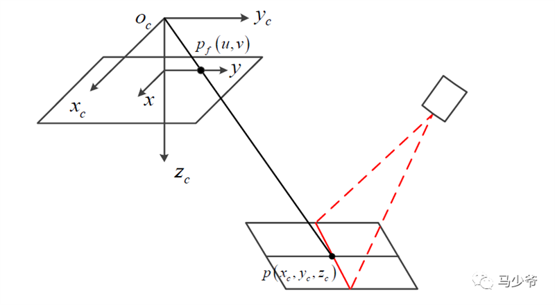
Structured light visual projection imaging model:
The plane equation of structured light in the camera coordinate system is:

Based on the image coordinates of laser stripe feature points, their three-dimensional coordinates in the camera coordinate system can be obtained
Camera parameter calibration:
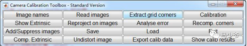
Using the camera calibration method based on 2D checkerboard proposed by Zhang Zhengyou, the camera parameters are calibrated using Matlab camera calibration tool.
Camera calibration toolbox main window:
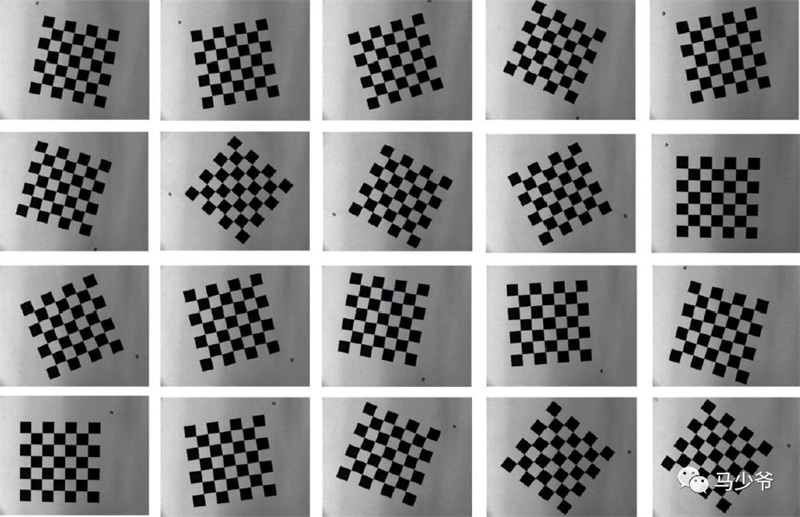
Checkerboard images for camera calibration:
Relevant references can be found in Zhang Zhengyou's paper:
Zhang Z. A flexible new technique for camera calibration[J]. IEEE Transactions on pattern analysis and machine intelligence, 2000, 22(11): 1330-1334.
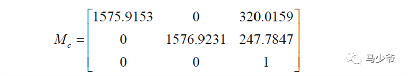
Obtain the camera's internal parameter matrix:
Calibration of structured light plane parameters:
Firstly, the laser projects a structured light plane onto a flat chessboard to form laser stripes, and captures the laser stripe image through a CCD camera. Then, the image is processed to extract two feature points on the laser stripes. Control the robot to move according to certain constraints, moving from one calibration position to another, thereby generating two non collinear laser stripes. Use the same image processing method mentioned above to extract the two feature points on the laser stripes again. Finally, use the four points on the structured light plane to determine the parameters of the structured light plane equation. This method can simultaneously calibrate the parameters of the structured light plane equation during the camera parameter calibration process. Meanwhile, this method does not require the processing of high-precision 3D calibration targets or manual measurement, and the calibration process is simple and practical.
Test equipment:
A six degree of freedom robot, a CCD industrial camera, a laser, and a flat checkerboard target.
Schematic diagram of structured light plane parameter calibration system:
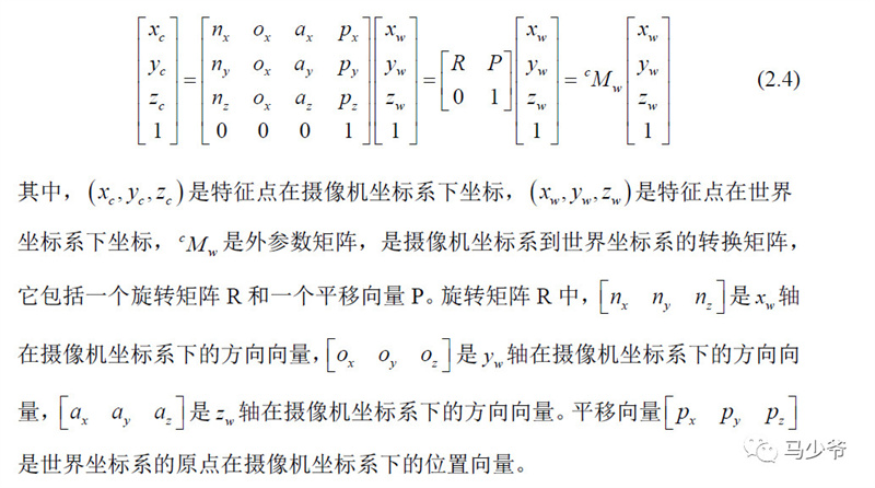
The camera coordinate system is located at the center of the camera, while the world coordinate system is located on a flat checkerboard target. The correspondence between the coordinates of a feature point in the camera coordinate system and its coordinates in the world coordinate system can be expressed using the following equation:
The calibration process is as follows:
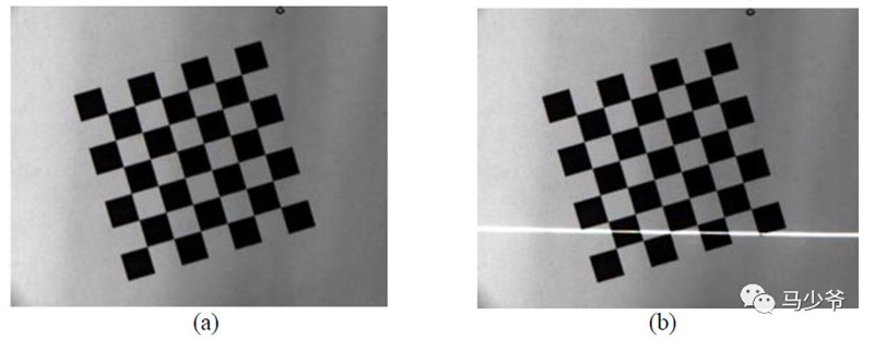
(1) Image acquisition:
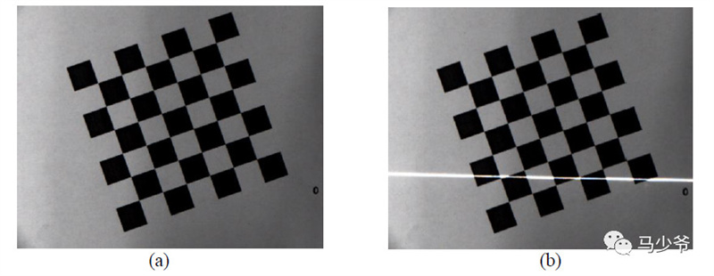
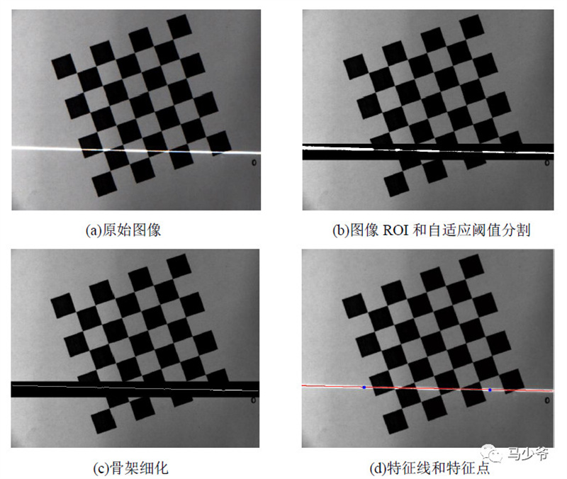
The acquisition of images is completed simultaneously during the camera parameter calibration process. Firstly, place the chessboard grid on the workbench, and at this initial position, capture a picture using a camera, as shown in Figure (a). Keep the position and posture of the camera and chessboard unchanged, turn on the laser to project the stripes onto the chessboard, and then capture an image as shown in Figure (b):
Then change the relative pose of the chessboard and the camera so that the two laser stripes formed before and after are not collinear in space, and a unique structured light plane can be determined.
(2) Image processing:
The purpose of image processing is to extract the image coordinates of feature points on laser stripes.
It is divided into regions of interest (ROI) determination, adaptive threshold segmentation, skeleton refinement, and feature point calculation.
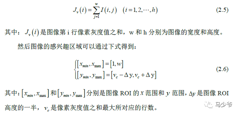
1) Image ROI determination
By observing the image, it can be seen that the laser stripes are roughly parallel to the u-axis of the image, and the grayscale values of the pixels at the laser stripes are higher than those of other pixels in the image. Therefore, the ROI of the image can be obtained by summing the grayscale values of each row of pixels:
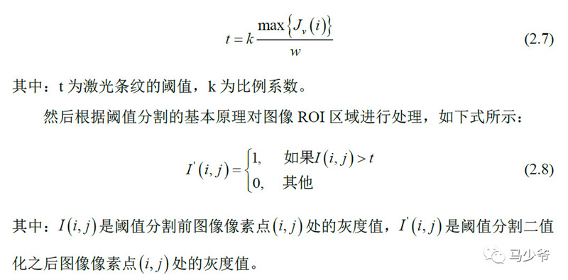
2) Threshold segmentation
Threshold segmentation can be divided into global threshold segmentation, local threshold segmentation, and adaptive threshold segmentation. The most commonly used adaptive threshold segmentation method is the Otsu method, which uses statistical methods to determine the optimal threshold and is suitable for general images, but not very suitable for segmentation of laser stripes on chessboards.
Based on the fact that the grayscale value of the laser stripes in the image is higher than that of other pixels and the region where the laser stripes are located is relatively concentrated, the adaptive threshold of the laser stripes is calculated using the sum of the grayscale values of row pixels in the image ROI:
3) Skeleton refinement:
After adaptive threshold segmentation, the laser stripes have a certain width, which requires a large amount of computation and low accuracy for direct processing. It is necessary to refine the image skeleton to obtain single pixel lines.
Using the fast skeleton refinement method proposed in the following literature:

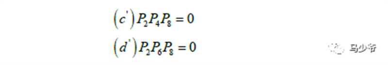
This method iteratively extracts the image skeleton, with each iteration process divided into two steps. The first step is to remove the points at the southeast edge and northwest corner, and the second step is to remove the points at the northwest edge and southeast corner.
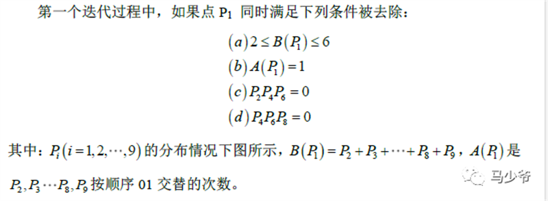
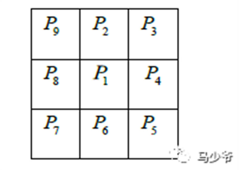
The distribution of Pi is as follows:
The second iteration process changes the c and d conditions of the above conditions to:
4) Feature extraction:
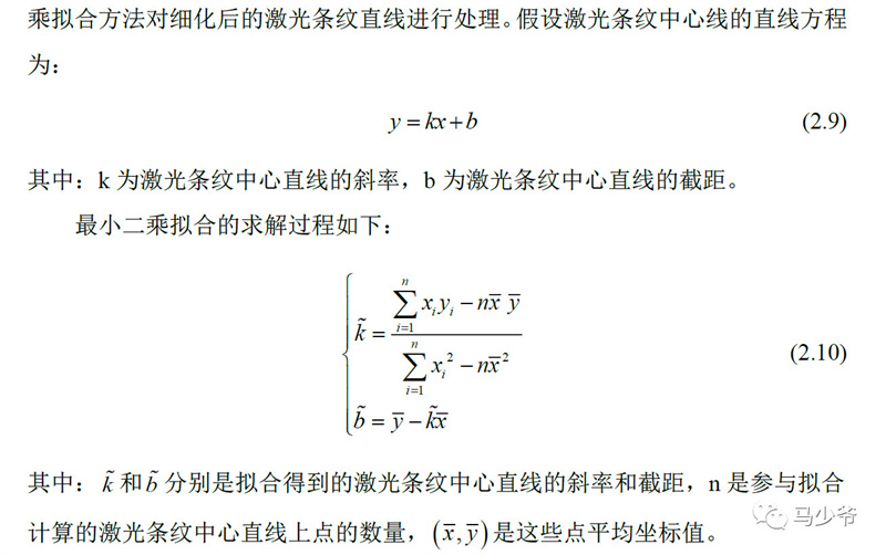
Select two points on the centerline of the laser stripe as the feature points of the laser stripe. In order to improve the accuracy of extracting the centerline of the laser stripe, the least squares fitting method is used to process the refined straight lines of the laser stripe.
The process of extracting laser stripe feature points is as follows:
Calibrate the relationship between any point in the chessboard plane and the normal vector
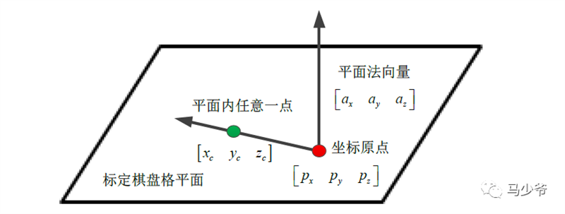
As can be seen from the above figure:

According to the relationship between the image coordinates Pf of feature points and their three-dimensional coordinates P in the camera coordinate system:

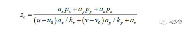
Obtain the zc coordinates of any point on the chessboard in the camera coordinate system
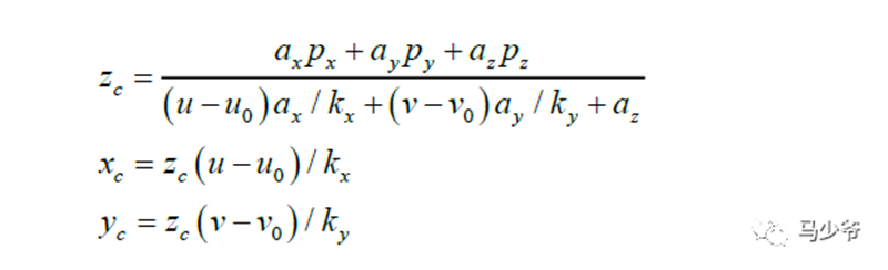
Obtain the coordinate values of laser stripe feature points in the camera coordinate system
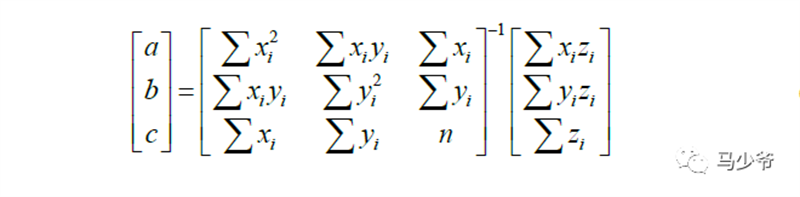
At this point, the image coordinates of four laser stripe feature points are obtained. The coordinates of the four laser stripe feature points in the camera coordinate system are obtained from the above equation. Since the three points determine a plane equation, the least squares method is used to calculate the structured light plane equation as follows:
At this point, the calibration of the parameters for the structured light plane equation has been completed.
Reference: Research on Weld seam recognition and tracking technology based on structured light vision [D] Institute of Automation, Chinese Academy of Sciences University of Chinese Academy of Sciences two thousand and nineteen
Note: This article (including images) is a reprint, and the copyright of the article belongs to the original author. If there is any infringement, please contact us to delete it.