1、 Composition of Industrial CCD:
A typical machine vision system can be divided into three parts: image acquisition, image processing, and motion control. The PC based visual system consists of several parts as shown in the following figure:
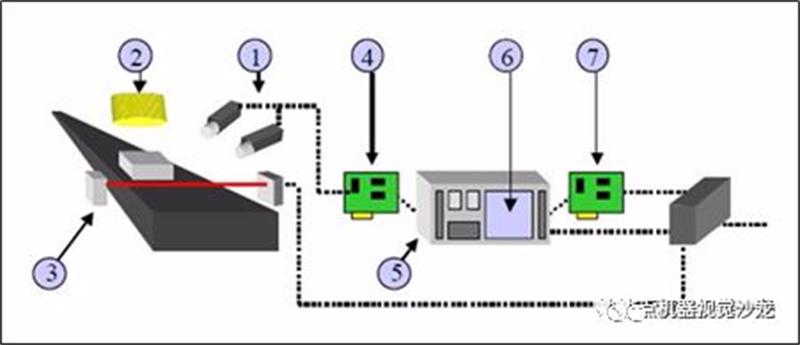
① Industrial cameras and industrial lenses - this part belongs to imaging devices, and the typical visual system is composed of one or more sets of such imaging systems. If there are multiple cameras, the image data may be obtained by switching the image card, or by synchronously controlling the acquisition of data from multiple camera channels. According to the application requirements, the camera may output standard monochrome video (RS-170/CCIR), composite signal (Y/C), RGB signal, or non-standard progressive scanning signal, line scanning signal, high-resolution signal, etc.
② Light source - as an auxiliary imaging device, it often plays a crucial role in the quality of imaging (some data suggests that light source can account for over 30% of the imaging effect), and various shapes of LED lights, high-frequency fluorescent lights, fiber optic halogen lights, etc. are easy to obtain.
③ Sensors - typically appearing in the form of fiber optic switches, proximity switches, etc., are used to determine the position and status of the measured object (externally triggered) and inform the image sensor to perform the correct acquisition.
④ Image capture card - usually installed in the form of an inserted card in a PC, the main job of the image capture card is to transfer the images output by the camera to the computer host. It converts analog or digital signals from the camera into a certain format of image data stream, and can control some parameters of the camera, such as trigger signal, exposure/integration time, shutter speed, etc. Image capture cards often have different hardware structures for different types of cameras, as well as different bus forms, such as PCI, PCI64, Compact PCI, PC104, ISA, etc.
⑤ PC Platform - The computer is the core of a PC style visual system, where image data processing and the majority of control logic are completed. For detection type applications, a higher frequency CPU is usually required to reduce processing time. At the same time, in order to reduce the interference of electromagnetic, vibration, dust, temperature, etc. in industrial sites, it is necessary to choose industrial grade computers.
⑥ Visual processing software - Machine vision software is used to process input image data, and then obtain results through certain operations. The output results may include PASS/FAIL signals, coordinate positions, strings, etc. Common machine vision software appears in the form of C/C++image libraries, ActiveX controls, graphical programming environments, etc. It can be specialized (such as only used for LCD detection, BGA detection, template alignment, etc.) or general-purpose (including positioning, measurement, barcode/character recognition, spot detection, etc.).
⑦ Control unit (including I/O, motion control, level conversion unit, etc.) - Once visual software completes image analysis (unless only used for monitoring), it is immediately necessary to communicate with external units to complete control of the production process (output OK, NG signals). Simple control can directly utilize the built-in I/O of some image acquisition cards, while relatively complex logic/motion control must rely on additional programmable logic control units/motion control cards to achieve necessary actions.
Introduction to the Principles of Industrial Cameras
The most essential function of industrial cameras is to convert light signals into ordered electrical signals. Choosing a suitable camera is also an important part of machine vision system design. The choice of camera not only directly determines the resolution and quality of the captured images, but also is directly related to the operating mode of the entire system.
1. Camera chip type:
In general, industrial cameras can be divided into CCD cameras and CMOS cameras according to the mainstream chip types in the market. Of course, there are also some other chips, such as the Super CCD chip produced by Fuji. The CCD and CMOS of digital cameras are deeply hidden inside the camera, and even if there is a chance to see their appearance, it is difficult to distinguish them.
The working principle of CCD chip is shown in the figure:
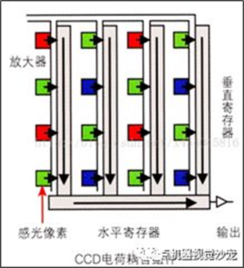
After receiving light at the photosensitive point, the photosensitive element generates a corresponding current, which corresponds to the intensity of the light. Therefore, the electrical signal directly output by the photosensitive element is analog. In CCD sensors, each photosensitive element does not perform further processing on this, but instead outputs it directly to the vertical register, transfers it to the horizontal register, and finally forms a unified output. Due to the weak electrical signal generated by the photosensitive element and the significant voltage loss generated during this process, it is not possible to directly perform analog-to-digital conversion work. Therefore, these output data must be uniformly amplified - this task is specifically handled by the amplifier in the CCD sensor. After being processed by the amplifier, the electrical signal strength of each pixel is increased by the same amplitude; Due to the signal being amplified by only one amplifier, there is less noise generated. However, due to the fact that CCD itself cannot directly convert analog signals into digital signals, a specialized analog-to-digital conversion chip is needed for processing, and the final output is in the form of a binary digital image matrix to a specialized DSP processing chip.
The working principle of CMOS is shown in the figure:
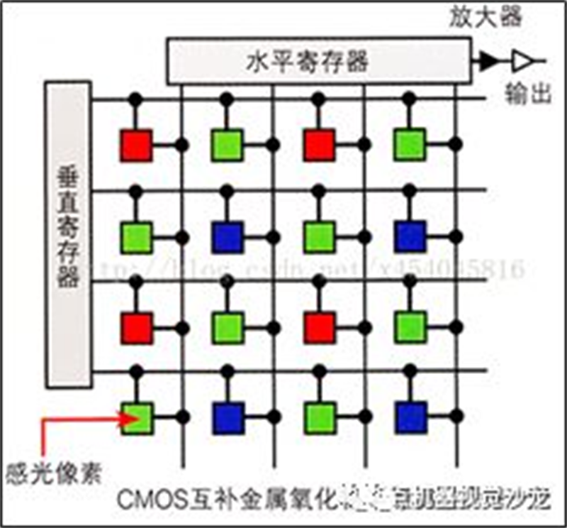
For CMOS sensors, the above workflow is completely unsuitable. Each photosensitive element in CMOS sensors directly integrates an amplifier and analog-to-digital conversion logic. When the photodiode receives light and generates an analog electrical signal, the electrical signal is first amplified by the amplifier in the photosensitive element, and then directly converted into the corresponding digital signal. In other words, in CMOS sensors, each photosensitive element can generate the final digital output, and the resulting digital signal is combined and directly sent to the DSP chip for processing. The problem precisely occurs here. The amplifier in CMOS photosensitive elements is a simulator device, which cannot ensure that the magnification of each pixel is strictly consistent, resulting in the enlarged image data not representing the original appearance of the photographed object - reflected in the final output result, there is a lot of noise in the image, and the quality is significantly lower than that of CCD sensors. However, the technology in this area has been greatly improved.
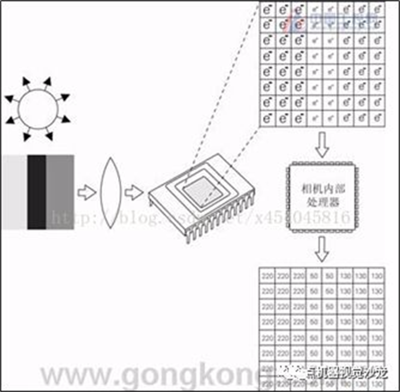
II The imaging principle of black and white cameras:
Taking the CCD principle as an example, the CCD principle is not complicated. We can imagine it as a memory chip with the top open. Therefore, the beam of light can be directed into the memory unit. According to the "photoelectric effect", these beams generate negative charges in the memory unit (upper right part in the figure below)
III Principles of Color Imaging:
The CCD chip converts photons into electrons, and in this process, the number of photons is proportional to the number of electrons. But photons also have another characteristic value - wavelength (which determines color), and this information is not converted into electrons in this process. Therefore, in this sense, CCD chips can all be referred to as color blindness. So the imaging of color cameras is slightly more complex, and currently there are mainly two methods: prism method and filter method. The following will introduce them separately:
Triprism method:
In order to obtain color information of light, it is easy to think of using a prism to divide the beam of light into monochromatic light, and then imaging them separately. Yes, the prism method is based on this principle, as shown in the following figure:
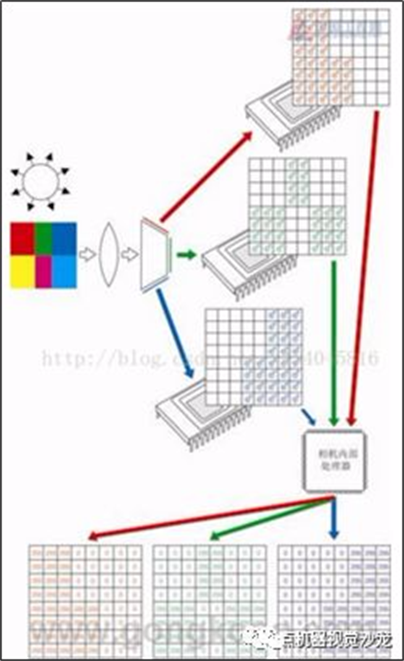
It divides the light emitted from the lens into three beams, each of which is filtered out by a different built-in grating to produce a certain three primary colors, and then uses three CCDs to sense the light separately. These images are then combined to create a high-resolution, color accurate image. A 3-megapixel camera is sensitive to light using three 3-megapixel CCDs. That is to say, it is possible to achieve same point synthesis, so the clarity of the photos taken is quite high. The main difficulty of this method is that it contains too much data. Before taking the next photo, you must clear and save the data stored in the camera's buffer. Therefore, these types of cameras have very high requirements for other components, and their prices are naturally very expensive.
Other color principles are omitted.
Introduction to common camera parameters:
1. Resolution: The number of pixels in each image captured by the camera. For industrial digital cameras, it generally corresponds directly to the number of pixels in the photoelectric sensor. For industrial digital analog cameras, it depends on the video format, which is 768 * 576 in PAL format and 640 * 480 in NTSC format.
2. Pixel Depth: refers to the number of bits per pixel of data, usually 8 bits (2 ^ 8), and for industrial digital cameras, there are usually 10 bits, 12 bits, etc.
3. Maximum Frame Rate/Line Rate: The rate at which a camera captures and transmits images. For an array camera, it is generally the number of frames per second (frames/sec.), while for a line array camera, it is the number of rows per second (Hz).
4. Exposure method and Shutter speed: For industrial linear array cameras, the exposure is done row by row, and fixed row frequency and external trigger synchronization acquisition methods can be selected. The exposure time can be consistent with the row cycle, or a fixed time can be set; There are several common methods for array cameras, including frame exposure, field exposure, and rolling row exposure. Industrial digital cameras generally provide the function of external trigger image acquisition. The shutter speed can generally reach 10 microseconds, and high-speed cameras can also be faster.
5. Pixel Size: The size and number of pixels (resolution) together determine the size of the camera target surface. At present, the pixel size of industrial digital cameras is generally 3 μ M-10 μ m. The smaller the pixel size, the more difficult it is to manufacture, and the less likely it is to improve image quality.
6. Spectral Range: Refers to the sensitivity of the pixel sensor to different light waves, with a general response range of 350nm to 1000nm. Some cameras add a filter in front of the target to filter out infrared light. If the system needs to be sensitive to infrared light, this filter can be removed.
Note: This article (including images) is a reprint, and the copyright of the article belongs to the original author. If there is any infringement, please contact us to delete it.