Autonomous vehicle work simultaneously through multiple types of sensors for environment perception and self perception. The robustness and accuracy of sensors are particularly important in the perception of autonomous vehicle.
Calibrating sensors is a necessary step and prerequisite for subsequent sensor fusion in autonomous driving perception systems. Its purpose is to transform two or more sensors into a unified spatiotemporal coordinate system, making sensor fusion meaningful and a key prerequisite for perception decision-making. Any sensor needs to be calibrated through experiments after manufacturing and installation to ensure that the sensor meets the design specifications and ensures the accuracy of measurement values. After the sensor is installed on the autonomous vehicle, it needs to be calibrated; Meanwhile, during vehicle operation, due to vibration and other reasons, the sensor position may deviate from its original position. Therefore, it is necessary to calibrate the sensor at regular intervals. Autonomous vehicle work simultaneously through multiple types of sensors for environment perception and self perception. The robustness and accuracy of sensors are particularly important in the perception of autonomous vehicle.
Camera calibration
The car mounted camera is installed on the vehicle at a certain angle and position. In order to correspond the environmental data collected by the car mounted camera with the real objects in the vehicle's driving environment, that is, to find the conversion relationship between the point coordinates in the pixel coordinate system generated by the car mounted camera and the point coordinates in the camera's environmental coordinate system, camera calibration is required.
1.1 Camera internal parameter calibration
1.1.1 Establishment of camera model
Through the mutual transformation relationship between the environmental coordinate system, camera coordinate system, image physical coordinate system, and image pixel coordinate system, we can calculate the transformation relationship between the environmental coordinate system and the image pixel coordinate system, that is
Point P on the real world. Its coordinates in the environmental coordinate system are (Xw, Yw, Zw), and its position in the image is (u, v). The two have the following relationship:
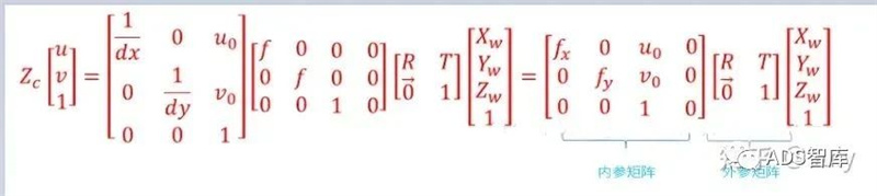
The conversion relationship between environmental coordinate system and image pixel coordinate system
For an inner parameter matrix, its four constants fx, fy, Uo, Vo. It is related to the design technical indicators of the camera, such as focal length, main point, and sensor, and is independent of external factors such as surrounding environment and camera position, so it is called the internal reference of the camera. The internal reference is determined when the camera leaves the factory. However, due to manufacturing processes and other issues, even cameras produced on the same production line have slight differences in internal parameters, so it is often necessary to determine the camera's internal parameters through experiments. The calibration of a monocular camera usually refers to determining the camera's internal parameters through experimental means.
The extrinsic matrix includes a rotation matrix and a translation matrix, which together describe how to convert a point from the world coordinate system to the camera coordinate system. In computer vision, the process of determining the extrinsic matrix is commonly referred to as visual localization. After the installation of on-board camera for autonomous vehicle, the camera position under the vehicle coordinate system needs to be calibrated. In addition, due to the turbulence and vibration of the car, the position of the on-board camera will change slowly over time. Therefore, autonomous vehicle need to recalibrate the camera position regularly, a process called calibration.
1.1.2 Camera distortion correction
In practical use, cameras cannot accurately perform perspective projection according to the ideal pinhole camera model, and there is usually lens distortion, that is, there is a certain optical distortion error between the image generated by the object on the actual camera imaging plane and the ideal imaging, and the distortion error is mainly radial distortion error and tangential distortion error.
Radial distortion: Due to the characteristics of a lens, light rays are prone to small or significant bending at the edges of the camera lens, known as radial distortion. This distortion is more pronounced in ordinary and inexpensive lenses, and radial distortion mainly includes two types: barrel distortion and pillow distortion. Barrel distortion is a distortion phenomenon caused by the lens and lens group structure in the lens, resulting in a barrel shaped expansion of the imaging image. Usually, when using a wide-angle lens or the wide-angle end of a zoom lens, it is easier to detect barrel distortion. Pillow distortion is the phenomenon of the image shrinking towards the center caused by the lens. People are more likely to notice pillow shaped distortion when using the telephoto end of a zoom lens.
Tangential distortion: It is caused by the lens itself not being parallel to the camera sensor plane (imaging plane) or image plane, which is often caused by installation deviation when the lens is pasted onto the lens module.
In computer vision, radial distortion has a significant impact on scene reconstruction. The auto drive system's perception of the environment requires that the camera can achieve high-precision reconstruction of the surrounding environment. If the distortion is not corrected, accurate environmental information cannot be obtained. For example, the target in the environment may appear in any area of the image. If the distortion is not corrected, the position and size of the target obtained through visual technology are often inaccurate, which will directly affect the driving safety of autonomous vehicle. In addition, the autonomous vehicle is equipped with multiple cameras, and if radial distortion is not considered at different locations, during the image stitching process, the corresponding features will be mismatched, resulting in the blurred effect of the stitching image.
For general cameras, the radial distortion of the image is often described as a low order polynomial model. If (u, v) is the coordinates of the corrected point and (u ', u') is the coordinates of the uncorrected point, then the transformation between the two can be determined by the following formula:
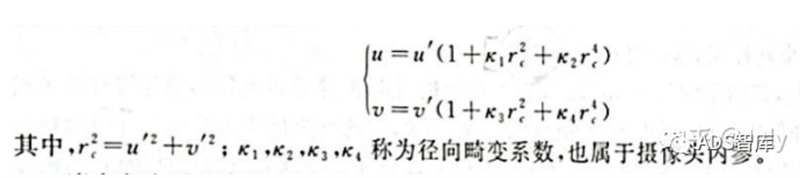
Low order polynomial model with radial distortion
On the other hand, for tangential distortion, two additional parameters p1 and p2 can be used to correct it:
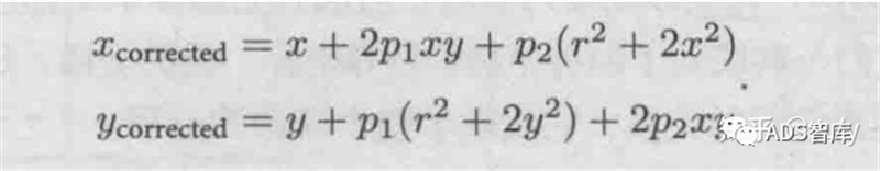
Tangential distortion low order polynomial model
1.1.3 Camera internal calibration method
At present, the calibration of distortion parameters is generally carried out simultaneously with other internal parameters. The most widely used method at present is the Zhang Zhengyou calibration method proposed by Zhang Zhengyou in 2000. The Zhang Zhengyou calibration method finds the inner corner points of the chessboard calibration board in each image by shooting the chessboard calibration board at different positions, and establishes a matrix through the correspondence between the inner corner points

The constraint is used to restore the inner parameter matrix K.
1.2 Calibration of extrinsic parameters between cameras
In autonomous vehicle, in order to reduce the blind area of perception as much as possible, multi camera mode is often used. The process of determining the relative positional relationship between multiple cameras is called camera extrinsic calibration.
From another perspective, camera extrinsic calibration can also be referred to as the "attitude estimation" problem. The relative pose [R | t] between two cameras has 6 degrees of freedom (spatial position and rotation relationship). In theory, as long as both cameras simultaneously capture 3 points in space, their relative pose can be restored. The problem of restoring the relative pose between cameras from three corresponding points is called the Perspective 3 Point Problem (P3P). In reality, more than three points are often used to restore relative posture to improve robustness, and the P3P problem has been extended to the PnP problem.
Initially, researchers used the Direct Linear Transform (DLT) to solve the PnP problem. Later, in order to improve accuracy, researchers proposed robust linearization of the reprojection error and began using an iterative method to solve the PnP problem. As a result, they proposed the famous Bundle Adjustment (BA) method in attitude estimation.
Calibration of LiDAR
One of the main sensors of the LiDAR autonomous driving platform plays an important role in perception and positioning. Like cameras, LiDAR also needs to calibrate its internal and external parameters before use. Internal calibration refers to the conversion relationship between the internal laser emitter coordinate system and the radar's own coordinate system, which has been calibrated before leaving the factory and can be used directly. What the auto drive system needs to do is external parameter calibration, that is, the relationship between the laser radar's own coordinate system and the car body's coordinate system.
The LiDAR is rigidly connected to the vehicle body, and the relative attitude and displacement between the two remain fixed. In order to establish the relative coordinate relationship between LiDARs and between LiDARs and vehicles, it is necessary to calibrate the installation of LiDARs and convert LiDAR data from the LiDAR coordinate system to the vehicle coordinate system.
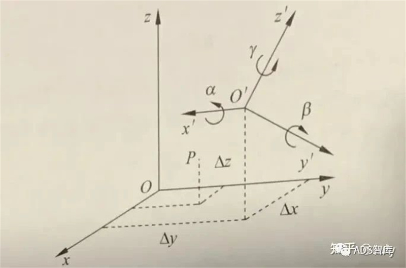
Vehicle coordinate system and LiDAR coordinate system
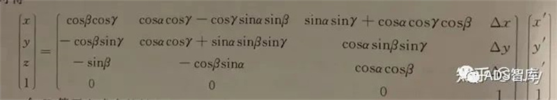
By collecting the true coordinates of the same point in two coordinate systems through experiments, that is, the point with the same name, a series of equations can be established to calculate these 16 unknown parameters. In addition, on autonomous vehicle, it is usually necessary to calibrate the laser radar and inertial navigation unit (IMU) coordinate system, and establish the relationship between the laser radar and the vehicle body coordinate system.
2.1 Calibration between LiDAR and LiDAR
For autonomous vehicle, sometimes there are multiple lidars, and the external environment acquired by each lidar must be accurately mapped to the vehicle body coordinate system. Therefore, when there are multiple LiDARs, it is necessary to calibrate and calibrate the relative positions of multiple LiDARs.
There are various ways to calibrate the external parameters between LiDARs, among which the most commonly used is to indirectly derive the coordinate conversion relationship between LiDARs and the vehicle body through the coordinate conversion relationship between different LiDARs.
2.2 Calibration of LiDAR and Camera
On autonomous vehicles, the LiDAR is rigidly connected to the autonomous vehicle, and the relative attitude and displacement between the two remain fixed. Therefore, the data points obtained by LiDAR scanning have unique positional coordinates corresponding to them in the environmental coordinate system. Similarly, the camera also has a unique position coordinate in the environmental coordinate system, so there is a fixed coordinate conversion between the LiDAR and the camera. The joint calibration of LiDAR and camera is achieved by extracting the corresponding feature points of the calibration object on the single line LiDAR and image, completing the unity of multiple sensor coordinates such as single line LiDAR coordinates, camera coordinates, and image pixel coordinates, and achieving spatial calibration of LiDAR and camera.
After completing camera extrinsic calibration and LiDAR extrinsic calibration, the relationship between the two can actually be completely determined, and the LiDAR scanning points can be projected onto the image pixel coordinate system.
Similar to the camera's internal calibration method, the external calibration of LiDAR and camera can also be done using the calibration board's calibration method.
Note: This article (including images) is a reprint, and the copyright of the article belongs to the original author. If there is any infringement, please contact us to delete it.