Hello everyone, welcome to follow the series of technical sharing articles (Collaborative Robot ROS Development) brought by Aobo Academy. In the previous course, we explained the relevant knowledge of robot hand eye calibration principles. Now, let's learn about Aobo E5 robotic arm and camera hand eye calibration.
Environment version
Host system version: Windwos10 64 bit
Processor model: Intel-i7
Virtual Machine Version: VMware Workstation 16 Pro
Virtual Machine System: Ubuntu 18.04.6 LTS
ROS version: Melodic
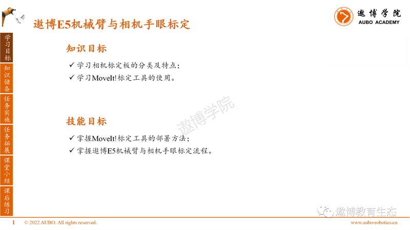
Learning objectives
Knowledge reserve
The following will introduce the knowledge points of this section:
Firstly, learn the classification and characteristics of camera calibration boards.
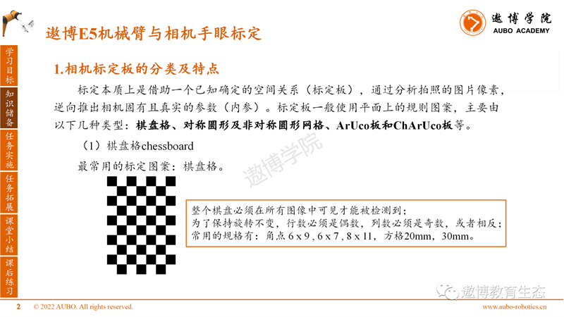
Calibration essentially relies on a known and determined spatial relationship (calibration board), analyzing the pixels of the photographed image, and inferring the intrinsic and real parameters (internal parameters) of the camera in reverse. Calibration boards generally use regular patterns on a plane, mainly consisting of the following types: checkerboard, symmetric and asymmetric circular grids, ArUco boards, and ChArUco boards.
(1) Chessboard, the most commonly used calibration pattern.
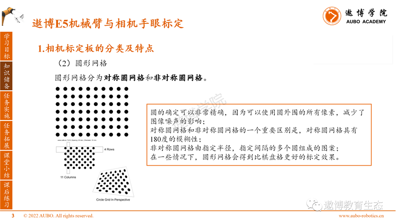
(2) Circular grid
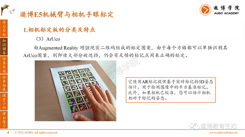
(3)ArUco
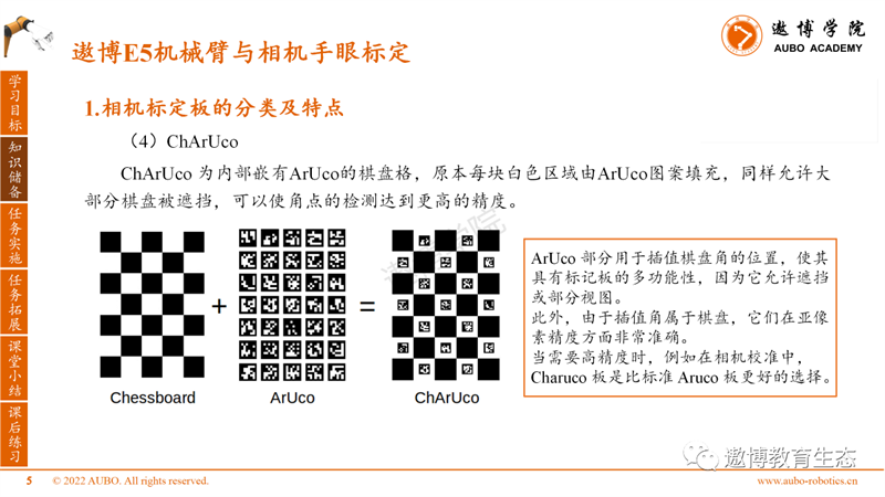
(4)ChArUco
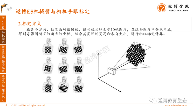
2. Calibration method
Task implementation
This course adopts an eye in hand approach for hand eye calibration, using the tool MoveIt! Calibration.
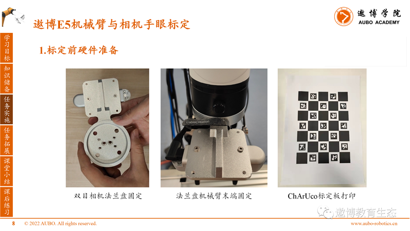
1. Hardware preparation before calibration
Fix the flange of the binocular camera. Fix the end of the flange mechanical arm. Print the ChArUco calibration board on 100% A4 paper.
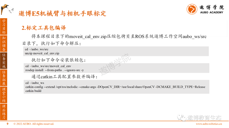
2. Calibration toolkit compilation
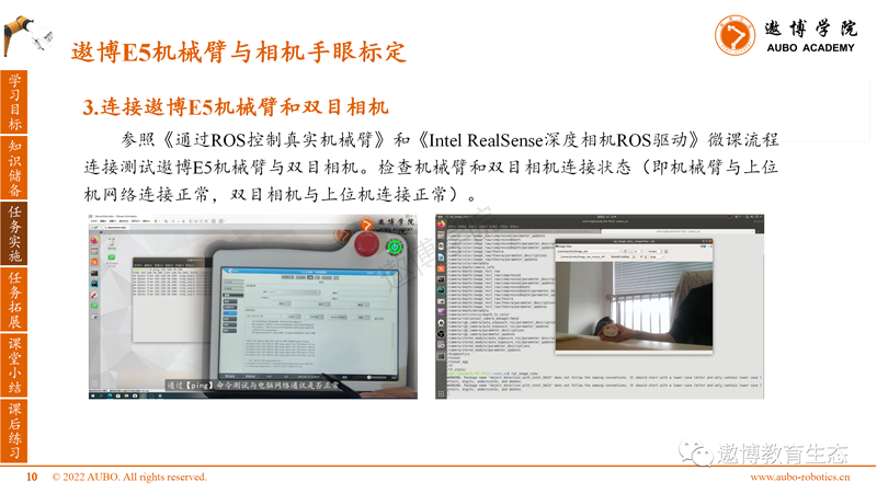
3. Connect the Aobo E5 robotic arm to the binocular camera
4. Hand eye calibration
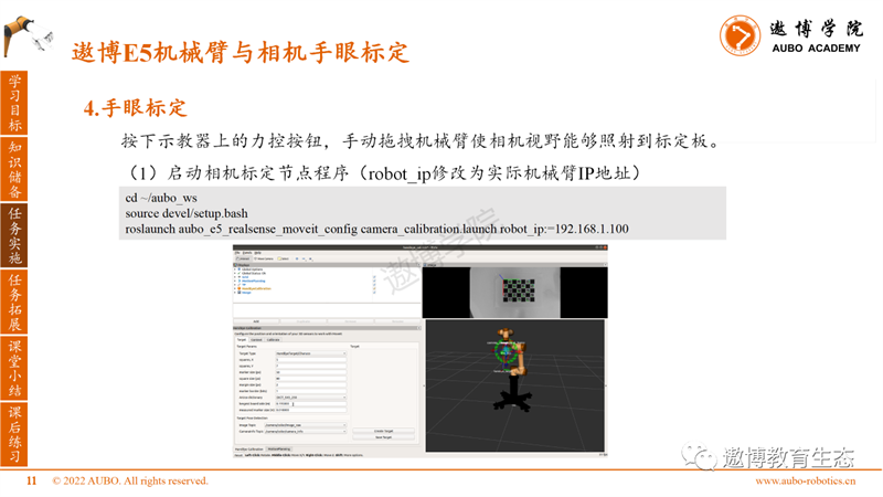
Press the force control button on the teaching pendant and manually drag the robotic arm to allow the camera's field of view to shine onto the calibration board.
(1) Start the camera calibration node program (robot_ip is modified to the actual robotic arm IP address)
(2) Calibration component Target tab configuration
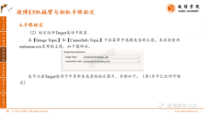
In the Target Parameters section of the Target tab, we will use the default target parameters. Select [HandEyeTarget/Caruco] as the calibration board type Target Type, and the other parameters are shown in the figure.

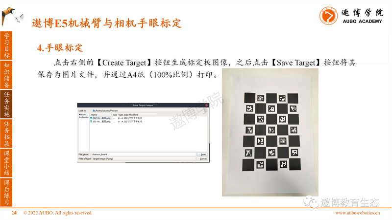
Click the [Create Target] button on the right to generate the calibration board image, then click the [Save Target] button to save it as an image file and print it on A4 paper (100% scale).
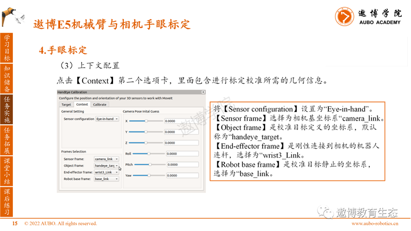
(3) Context configuration
Click on the second tab of [Context], which contains the geometric information required for calibration. Set the Sensor configuration to "Eye in hand".
Select "camera frame" as the camera base coordinate system.
The Object frame is the coordinate system defined by the calibration target, which is called "handeye_target" by default.
The "End effector frame" is a robot link that is rigidly connected to the camera, selected as "writt3-Link".
The Robot base frame is the coordinate system in which the calibration target is stationary, selected as "baseunlink".
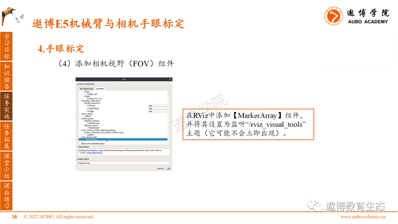
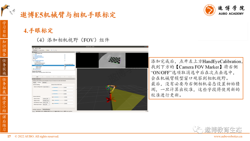
(4) Add Camera Field of View (FOV) component
Add a MarkerArray component to RViz and set it to listen to the "/rviz_visual_tools" theme (which may not appear immediately).
After adding, click on HandEyeCalibration in the upper left corner, find the Camera FOV Marker below, uncheck the "ON/OFF" option on the right side, and click again to select it. The camera field of view will be observed in the robotic arm model window.
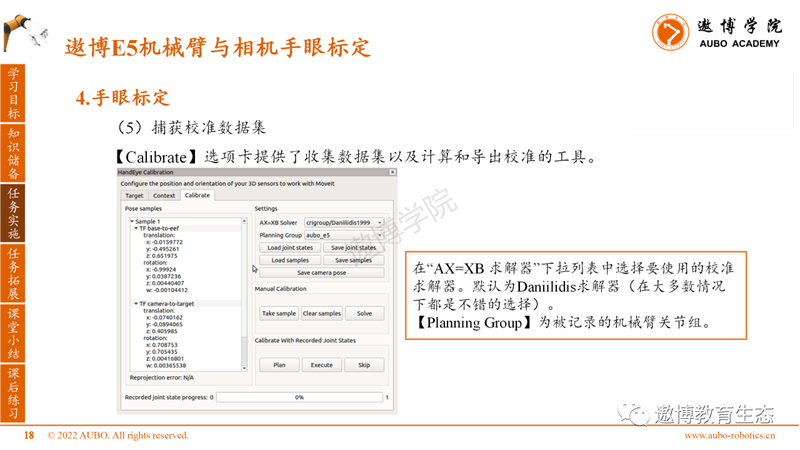
(5) Capture calibration dataset
The Calibrate tab provides tools for collecting datasets and calculating and exporting calibrations.
Select the calibration solver you want to use from the "AX=XB Solver" drop-down list. The default is the Daniilidis solver (which is a good choice in most cases).
The Planning Group is the joint group of the recorded robotic arm.
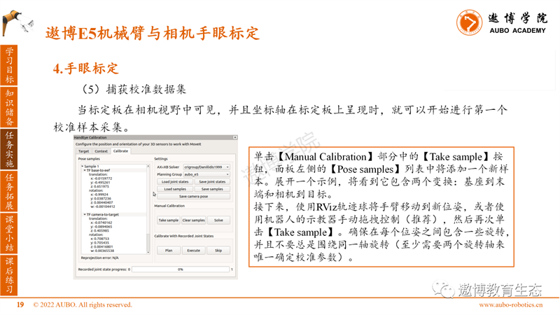
When the calibration board is visible in the camera's field of view and the coordinate axis is presented on the calibration board, the first calibration sample collection can begin.
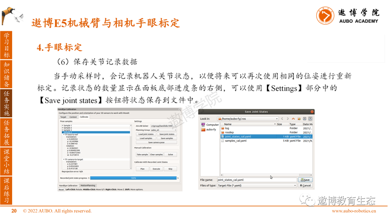
(6) Save joint record data
When manually sampling, the robot joint status is recorded so that it can be recalibrated using the same pose again in the future. The number of recorded states is displayed on the right side of the progress bar at the bottom of the panel. You can use the Save joint states button in the Settings section to save the states to a file.
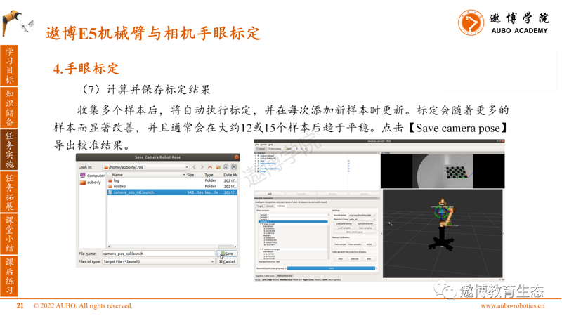
(7) Calculate and save calibration results
After collecting multiple samples, calibration will be automatically performed and updated every time a new sample is added. Calibration will significantly improve with more samples and usually tends to stabilize after approximately 12 or 15 samples. Click on [Save camera pose] to export the calibration results.
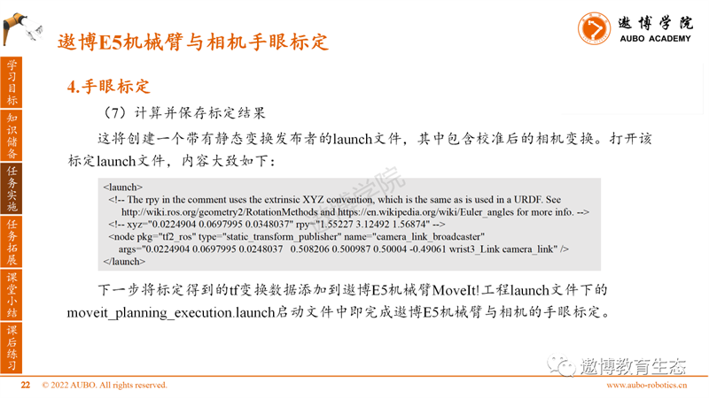
This will create a launch file with a static transformation publisher, which includes calibrated camera transformations. Open the calibration launch file, and the content is roughly as follows.
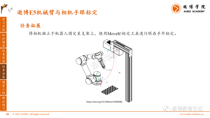
Task Expansion
Fix the camera independently of the robot to the bracket and use MoveIt! Calibration tools perform eye to hand calibration.
Classroom Summary
1. The OpenCV version used in Ubuntu 18.04 system is 3.2, and there is a bug in the ArUco library. It is recommended not to use ArUco type calibration boards for calibration.
During the calibration process, it is necessary to ensure that the position of the calibration board is fixed and the camera's field of view can detect the coordinate axis on the calibration board. Otherwise, abnormal points will be introduced, leading to an increase in overall calibration error.
After class exercises
1. Fix the RealSense binocular camera to the end of the Aobo E5 robotic arm for hand eye calibration.
2. Obtain pose transformation data of objects with ArUco codes relative to the base of the robotic arm, and test the accuracy of calibration parameters.
In the upcoming ROS course, we will explain the voice interaction control of the Aobo E5 robotic arm. Please continue to follow us.
Note: This article (including images) is a reprint, and the copyright of the article belongs to the original author. If there is any infringement, please contact us to delete it.