1. Camera selection
(1) Classification of industrial digital cameras:
Industrial cameras can be divided into CCD cameras and CMOS cameras according to chip types;
According to the output color, it can be divided into monochrome (black and white) cameras and color cameras;
According to the structural characteristics of sensors, they can be divided into linear array cameras (black and white cameras, 3Line color cameras, 3CCD color cameras (splitter prisms), area array cameras (black and white cameras, Bayer color cameras, and 3CCD color cameras (splitter prisms);
According to the output signal method, it can be divided into analog cameras (PAL (CCIR for black and white), NTSC (EIA for black and white), digital cameras (IEEE1394, USB2.0, Camera Link, GigE);
According to the scanning method, it can be divided into interlaced scanning cameras and progressive scanning cameras;
According to the resolution size, it can be divided into regular resolution cameras and high-resolution cameras;
According to the output signal speed, it can be divided into ordinary speed cameras and high-speed cameras;
According to the response frequency range, it can be divided into visible light (ordinary) cameras, infrared cameras, ultraviolet cameras, etc.
(2) The main parameters of the camera
a. Resolution
Resolution is the most basic parameter of a camera, determined by the resolution of the chip used by the camera, and is the number of pixels arranged on the chip target surface.
The resolution of an array camera is usually represented by two numbers: horizontal and vertical resolution, such as 1920 (H) x 1080 (V). The first number represents the number of pixels per row, which means there are a total of 1920 pixels. The second number represents the number of rows of pixels, which is 1080 rows. Nowadays, the resolution of a camera usually represents how much K, such as 1K (1024), 2K (2048), 3K (4096), etc.
The resolution of the camera has a significant impact on image quality when collecting images. When imaging the same field of view (range of scenery), the higher the resolution, the more obvious the display of details.
b. Speed (Maximum Frame Rate/Line Rate)
The frame rate/row rate of the camera represents the frequency at which the camera captures images. Typically, frame rate is used for array cameras, measured in fps (Frame Per second). For example, 30fps indicates that the camera can capture up to 30 frames of images within 1 second; Linear array cameras usually use line frequency as the unit KHz, for example, 12KHz indicates that the camera can capture up to 12000 lines of image data within 1 second.
The rate at which a camera captures and transmits images is generally the number of frames per second (Frames/Sec.) for an array camera, and the number of rows per second (Lines/Sec.) for a linear array camera.
Speed is an important parameter of a camera, and in practical applications, it is often necessary to image moving objects. The speed of the camera needs to meet certain requirements in order to accurately and clearly image objects. The frame rate and line rate of the camera are first affected by the frame rate and line rate of the chip, and the maximum design speed of the chip is mainly determined by the maximum clock that the chip can withstand.
c. Exposure method and shutter speed
For linear array cameras, the exposure method is row by row, and fixed row frequency and external trigger synchronization acquisition methods can be selected. The exposure time can be consistent with the row period, or a fixed time can be set; There are several common methods for array cameras, including frame exposure, field exposure, and scrolling row exposure. Digital cameras generally provide the function of external trigger image acquisition.
The shutter speed can generally reach 10 microseconds, and high-speed cameras can also be faster.
d. Noise
The noise of the camera refers to the unwanted signals outside the actual imaging target during the imaging process.
According to the European camera testing standard EMVA1288, the noise in cameras can be divided into two categories overall: one is statistical fluctuation noise that conforms to the Poisson distribution caused by effective signals, also known as shot noise. This type of noise is the same for any camera and is inevitable, with a definite calculation formula (the square of noise=the mean of the signal); The second type is the inherent signal independent noise of the camera itself, which is caused by image sensor readout circuits, camera signal processing and amplification circuits, etc. The inherent noise of each camera is different. In addition, for digital cameras, quantization noise is generated during analog conversion of video signals. The higher the quantization bit, the lower the noise.
e. Signal-to-noise ratio
The signal-to-noise ratio of a camera is defined as the ratio of the signal to noise in the image (the ratio of the average grayscale value of the effective signal to the root mean square of the noise), representing the quality of the image. The higher the signal-to-noise ratio of the image, the better the image quality. (Cameras with high signal-to-noise ratio perform better)
f. Dynamic range
The dynamic range of the camera indicates the range of light signals detected by the camera. The dynamic range can be defined by two methods. One is the optical dynamic range, which refers to the ratio of the maximum light intensity at saturation to the light intensity equivalent to noise output, determined by the characteristics of the chip. Another type is the electronic dynamic range, which refers to the ratio between saturation voltage and noise voltage.
For a fixed camera, its dynamic range is a constant value that does not change with external conditions. At the linear response, the dynamic range of the camera is defined as the ratio of saturated exposure to noise equivalent exposure:

The dynamic range can be expressed in terms of multiples, dB, or Bit. If the dynamic range is large, the camera has stronger adaptability to different lighting intensities.
g. Pixel/Pixel Depth
The digital signal output by a digital camera, namely the pixel grayscale value, has a special number of bits, which is called pixel depth. The number of bits per pixel of data is generally 8 bits, and for digital cameras, there are usually 10 bits, 12 bits, 14 bits, etc.
For black and white cameras, the orientation of this value is usually 8-16 bits. Pixel depth defines the number of gray levels in which the grayscale changes from dark to bright. For example, for an 8-bit camera, 0 represents full darkness and 255 represents full brightness. A number between 0 and 255 represents a certain brightness indicator. A 10 bit data has 1024 grayscales, while a 12 bit data has 4096 grayscales. We need to carefully consider whether very delicate grayscale levels are needed for every application. Raising from 8 bits to 10 bits or 12 bits can indeed enhance measurement accuracy, but it also reduces system speed and increases the difficulty of system integration (increasing cables and size). Therefore, we should also choose carefully.
h. Spectral response
Spectral response refers to the camera's ability to respond to light of different wavelengths, usually referring to the spectral response of the chip it uses. Usually represented by spectral curves, the horizontal axis represents different wavelengths, and the vertical axis represents quantum efficiency. According to the different response spectra, cameras can also be divided into visible light cameras (400nm-1000nm, with peaks between 500nm-600nm), infrared cameras (with response wavelengths above 700nm), and ultraviolet cameras (capable of responding to short waves between 200nm-400nm). We need to choose cameras with different spectral responses based on the different wavelengths of light emitted by the received object.
i. Optical interface/interface type
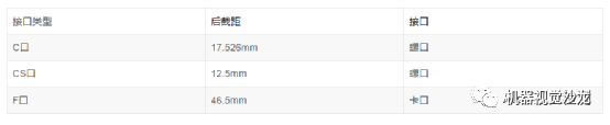
Optical interface refers to the interface between the camera and the lens, and commonly used lens interfaces include C port, CS port, and F port. The following table provides information about lens installation and rear focal length. The M42 lens adapter is derived from high-end camera standards. On the other hand, the Z-axis of the camera has been optimized based on the provided adapter. Generally, do not easily disassemble the lens adapter.
(3) Main interface types of industrial digital cameras
Mainly including: Usb2.0, IEEE 1394, CameraLink, GiggE, etc.

Currently, most industrial cameras on the market are based on CCD or CMOS chips.
CCD camera, also known as charge coupled device, is actually a method of organized storage of electrons coming out of image semiconductors. Advantages: High image quality, high sensitivity, and high contrast; Disadvantages: Blooming phenomenon, inability to directly access each pixel, and no on-chip processing function.
CMOS camera, also known as complementary metal oxide semiconductor, is actually just a technology that places transistors on silicon blocks, without any further meaning. CMOS can integrate photosensitive components, amplifiers, A/D converters, memory, digital signal processors, and computer interface control circuits on a single silicon wafer. Advantages: small size, simple structure, multiple on-chip processing functions, low power consumption, no Blooming phenomenon, direct access to a single pixel, high dynamic range (120dB), and higher frame rate; Disadvantages: poor consistency, poor optical sensitivity, and high noise.
Compared to CCD sensors, the random reading characteristics of CMOS sensors make it easy to achieve rectangular regions of interest (AOI) reading of images. This feature enables CMOS to achieve higher frame rates for smaller AOIs. Another advantage of CMOS sensors is their fast readout speed. The disadvantage of CMOS sensors is that their fill factor is very low, and micro mirrors are usually used to improve their fill factor.
The difference between CCD and CMOS:
- The advantage of CCD lies in its good imaging quality;
- CMOS is cheaper than CCD in price;
- CMOS power consumption is lower than CCD;
- CCD for dynamic measurement;
- CMOS is used for low-speed or static measurements. But now fully exposed CMOS can also be used for dynamic measurement;
- CCD is mainstream now, but CMOS is catching up, and CMOS is the future.
Note: CCD is global exposure, while CMOS has both global exposure and roller shutter exposure.
How to choose an industrial camera:
The first thing to understand is one's own inspection task, whether it is static or dynamic photography, what is the frequency of photography, whether it is defect detection or size measurement or positioning, what is the size of the product (shooting field of view), what precision needs to be achieved, the performance of the software used, the on-site environment, and whether there are any other special requirements.
If it is dynamic photography, what is the motion speed? Choose the minimum exposure time and whether to scan the camera line by line based on the motion speed; The frame rate of a camera (the highest shooting frequency) is related to pixels, and usually the higher the resolution, the lower the frame rate. The frame rate of different brands of industrial cameras may vary slightly.
The required resolution of an industrial camera can be calculated based on the different detection tasks, product size, required resolution, and software performance used; The most important consideration for the on-site environment is temperature, humidity, interference, and lighting conditions to choose different industrial cameras.
Consider the accuracy of the object to be observed or measured, and choose the resolution of an industrial camera based on the accuracy.
Camera pixel accuracy=size of unidirectional field of view/camera unidirectional resolution.
The camera's unidirectional resolution is equal to the size of the unidirectional field of view/theoretical accuracy.


实例1:
Example 2:
Assuming the detection of surface scratches on an object requires the size of the photographed object to be 10 * 8mm, and the required detection accuracy is 0.01mm.
Firstly, assuming that the field of view to be photographed is 12 * 10mm, the minimum resolution of the camera should be selected as (12/0.01) * (10/0.01)=1200 * 1000, which is approximately 1.2 million pixels. This means that if a pixel corresponds to a defect detection, the minimum resolution must be no less than 1.2 million pixels. However, commonly seen cameras on the market are 1.3 million pixel cameras, so generally 1.3 million pixel cameras are chosen.
But the actual problem is that if a pixel corresponds to a defect, such a system will definitely be extremely unstable, because any interfering pixel point can be mistaken for a defect. Therefore, in order to improve the accuracy and stability of the system, it is best to take the defect area to be 3 to 4 pixels or more. This way, the selected camera is only 1.3 million by 3, which means the minimum cannot be less than 3 million pixels. Usually, a camera with 3 million pixels is the best choice (I have seen the most people holding on to sub pixels and saying they want to achieve sub pixels with a resolution of a few tenths, so there is no need for such a high-resolution camera.
The minimum exposure time of a camera can determine the speed of the target's movement. Or conversely, the speed of the target's movement imposes a requirement on the minimum exposure time of the camera. Assuming our target motion speed is 1mm/S and our measurement accuracy is 0.01mm/pixel, we must consider that the drag caused by object motion must be less than our accuracy of 0.01mm, and the target movement of 0.01mm takes 10ms. This requires our camera's exposure time to be less than 10ms. If it is greater than this exposure time, the blur caused by object motion alone will be greater than 0.01, and our accuracy will no longer be able to reach 0.01.
Generally speaking, the blur caused by object motion should be one order of magnitude smaller than the measurement accuracy we require, which can reduce its impact on the system. Generally, our industrial cameras can achieve a maximum exposure time of tens to over a hundred microseconds. Such a short exposure time requires a high amount of light energy, so it is necessary to choose a suitable light source and light source controller.