Introduction to Camera Calibration
Firstly, there is distortion in the lens, which means that the captured image does not match the actual image and causes deformation. Even industrial lenses have a distortion rate of a few thousandths.
Secondly, no matter how high the mechanical structure accuracy of the lens and camera is, it is not easy or impossible to install the camera in a particularly straight position. Improper installation of the camera can also lead to errors. If you want to know the specific mathematical model, you can search for theoretical knowledge about camera calibration. I will focus on how to do it.
Calibration is to convert the above two things into normal.
Whether in image measurement or machine vision applications, camera parameter calibration is a crucial step, and the accuracy of the calibration results and the stability of the algorithm directly affect the accuracy of the results generated by camera operation.
Depth description:
1. Introduction to Camera Calibration Parameters
Internal reference: Determine the projection relationship of the camera from 3D space to 2D space.
The pinhole camera (FA lens camera) model has 6 parameters (f, kSx, Sy, Cx, Cy); The telecentric camera model has 5 parameters (f, Sx, Sy, Cx, Cy); A linear array camera has 11 parameters (f, k, Sx, Sy, Cx, Cy, Width, Height, Vx, Vy, Vz).
Among them:
F is the focal length;
K represents the level of radial distortion. If k is negative, the distortion is barrel distortion; if it is positive, the distortion is pillow distortion.
Sx, Sy is the scaling factor. For pinhole cameras (FA lenses), the distance between adjacent pixels in the horizontal and vertical directions of the image sensor is represented. The closer the initial value is to the true value, the faster the calculation speed. For telecentric camera models, represent the size of pixels in the world coordinate system.
Cx and Cy are the main points of the image. For a pinhole camera, this point is the vertical projection of the projection center on the imaging plane and also the center of radial distortion. For telecentric camera models, only the center of distortion is represented.
Vx, Vy, Vz: A linear array camera must have relative movement with the object being photographed in order to capture a useful image. This is the motion vector. Sx and Sy are the horizontal and vertical distances between adjacent pixels for a linear array camera.
2. Detailed Introduction to Calibration Board
Question 1: Can Halcon only use Halcon's dedicated calibration board?
Halcon provides a simple and accurate calibration operator and calibration assistant, which greatly facilitates users in practical use. There are two calibration methods in Halcon:
The calibration board defined by Halcon, which appears in the Halcon built-in routine
User defined calibration board, users can create calibration boards of any shape and form
So, Halcon is not limited to using dedicated calibration boards, but can also be calibrated using custom calibration boards.
Question 2: How is the Halcon calibration board generated?
Using the gen_caltab operator to create a calibration boardgen_caltab( : : XNum, YNum, MarkDist, DiameterRatio, CalPlateDescr, CalPlatePSFile : )
XNum:The number of black marked dots per line
YNum:The number of black marked dots in each column
MarkDist:The distance between the centers of two nearest black dots, in meters
DiameterRatio:The ratio of the diameter of a black dot to the distance between the centers of two dots
CalPlateDescr:The file path of the calibration board description file
CalPlatePSFile :Calibration board image file path, can be opened using Photoshop
Example :
gen_caltab( 7, 7, 0.1, 0.5, ‘caltab.descr’, ‘caltab.ps’)
Everyone can think about the meaning of each parameter for themselves
Rows :7
Number of columns :7
Black dot radius:0.05m
Center to center spacing of dots:0.1m
Question 3: How to place the Halcon calibration board and is there a limit on the number of photos taken?
It is not that the more calibration photos are taken, the higher the accuracy can be achieved. Halcon suggests shooting 9-16 photos and provides suggestions for placement. The calibration board occupies 1/3 to 1/4 of the calibration field of view, and the imaging grayscale value of the calibration board should be greater than 128 for smooth extraction.
Calibration steps
Note that only the array camera is introduced, other cameras and array channels are ideally the same.
1. Set camera internal initial values
Set the camera's internal initial values using the set_calib_data_cam_param operator
set_calib_data_cam_param( : : CalibDataID, CameraIdx, CameraType, CameraParam : )
CalibDataID:Calibration handle
CameraIdx:Camera serial number
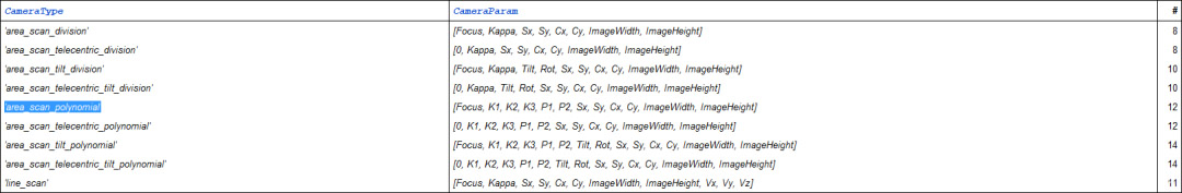
CameraType:Type of camera model; Area array camera DivisionDistortion model ’area_scan_division’;polynomial Distortion model ’area_scan_polynomial’。。。。。。
CameraParam :Parameters corresponding to the type of camera model; Division Distortion Model of Area Array Camera ’area_scan_division’([Focus, Kappa, Sx, Sy, Cx, Cy, ImageWidth, ImageHeight]);polynomial Distortion model’area_scan_polynomial’([Focus, K1, K2, K3, P1, P2, Sx, Sy, Cx, Cy, ImageWidth, ImageHeight])。。。。。。
Corresponding Table of Camera Model Types and Camera Parameters :
Techniques for selecting distortion types and determining parameters
Distortion model selection
division The distortion model is only suitable for situations with low accuracy and a small number of calibration images:
polynomial The distortion model corrects both radial and tangential distortions with high accuracy and takes a long time.
Parameter determination techniques
Focus Represent focal length, fill in according to our lens parameters, and fill in for telephoto lenses 0
Kappa For distortion size, it is filled in by default before calibration 0
Sx, Sy Fill in the pixel size of the camera with the width and height of the pixel. You can check the camera manual or consult the camera manufacturer.
Cx, Cy Fill in the center coordinates of the image
ImageWidth, ImageHeight Fill in the width and height of the image
2. Calibration board initialization
Using Operatorsset_calib_data_calib_object
For example:
CaltabDescr := ‘caltab_100mm.descr’set_calib_data_calib_object (CalibDataID, 0, CaltabDescr)
This is relatively simple, everyone can understand it by looking at the help, so we won't introduce it further
3、Create calibration data model
Using Operators create_calib_data( : : CalibSetup, NumCameras, NumCalibObjects : CalibDataID)
CalibSetup:Content created
NumCameras:Number of cameras
NumCalibObjects :Number of calibration items
CalibDataID:Calibration handle
For example: create_calib_data (‘calibration_object’, 1, 1, CalibDataID)
4. Obtain calibration images
The calibration board is a square with a size of 1/3 of the width of the area to be illuminated. The camera takes or reads 9-16 images, and the calibration board tries to cover the entire field of view when taking pictures; The diameter of the calibration board's dots cannot be less than 10 pixels.
5. Using images for camera intrinsic calibration and obtaining results
Method 1:
Using calibration images, directly use halcon Fully automatic, perform calibration find_calib_object (Image, CalibDataID, CameraIndex, 0, PoseIndex, [], [])
Obtain calibration data get_calib_data (CalibDataID, ‘camera’, 0, ‘type’, CameraType)
Method 2:
1. Find the calibration board area, determine the center of the circle, and load the results into the components
find_caltab(Image : CalPlate : CalPlateDescr, SizeGauss, MarkThresh, MinDiamMarks : )
find_marks_and_pose(Image, CalPlateRegion : : CalPlateDescr, StartCamParam, StartThresh, DeltaThresh, MinThresh, Alpha, MinContLength, MaxDiamMarks : RCoord, CCoord, StartPose)
set_calib_data_observ_points( : : CalibDataID, CameraIdx, CalibObjIdx, CalibObjPoseIdx, Row, Column, Index, Pose : )
Principle: Firstly, the find_caltab operator performs Gaussian filtering on the image (with a kernel size of SizeGauss), followed by threshold segmentation (with a threshold size of MarkThreshold) to identify the area of the calibration board; The find_marks.and_pose operator divides the circles in the region, and finds that the number, circumference, coordinates, etc. of the circles should be consistent with those in the calibration board description file. Otherwise, it will automatically adjust the StartThreshold, reducing it to DeltaThreshold step size MinDiamMarks ,Until the exact center is found.
2. Perform calibration
calibrate_cameras( : : CalibDataID : Error) Return average projection errorError
6. Using images for camera extrinsic calibration to obtain results
Camera extrinsic parameters: determine the relative positional relationship between the camera coordinate system and the world coordinate system
Where Pw is the world coordinate and Pc is the camera coordinate,T=(Tx,Ty,Tz)It's a translation vector,R=(a,b,r)Is the rotation matrix, which represents the rotation angle r around the Z-axis of the camera coordinate system; The rotation angle around the Y-axis of the camera coordinate system is b; The rotation angle around the X-axis of the camera coordinate system is a. Six parameters make up the camera extrinsic parameters(a,b,r,Tx,Ty,Tz)
And meet the following equation :
Pc=R*Pw+T
Specific steps:
set_calib_data_cam_param( : : CalibDataID, CameraIdx, CameraType, CameraParam : )
set_calib_data_calib_object( : : CalibDataID, CalibObjIdx, CalibObjDescr : )
find_calib_object(Image : : CalibDataID, CameraIdx, CalibObjIdx, CalibObjPoseIdx, GenParamName, GenParamValue : )
get_calib_data_observ_contours( : Contours : CalibDataID, ContourName, CameraIdx, CalibObjIdx, CalibObjPoseIdx : )
get_calib_data_observ_points( : : CalibDataID, CameraIdx, CalibObjIdx, CalibObjPoseIdx : Row, Column, Index, Pose)
set_origin_pose( : : PoseIn, DX, DY, DZ : PoseNewOrigin)
Halcon Camera calibration code and analysis
** Create calibration board
gen_caltab(7,7,0.008,0.5,'48_48mm.descr','48_48mm.ps')
*======= Calibrate internal parameters
dev_close_window ()
dev_open_window (0, 0, 652, 494, 'black', WindowHandle)
dev_update_off ()
dev_set_draw ('margin')
dev_set_line_width (3)
OpSystem := environment('OS')
set_display_font (WindowHandle, 14, 'mono', 'true', 'false')
* Calibrate the camera
StartCamPar := [0.0,0.0,0.0000299,0.0000299,4896/2,3264/2,4896,3264]
create_calib_data ('calibration_object', 1, 1, CalibDataID)
set_calib_data_cam_param (CalibDataID, 0, 'area_scan_telecentric_division', StartCamPar)
set_calib_data_calib_object (CalibDataID, 0, '48_48mm.descr')
for index := 1 to 13 by 1
read_image (Image, 'calibration 20/' + index + '.png')
get_image_size(Image, Width, Height)
dev_display (Image)
find_calib_object (Image, CalibDataID, 0, 0, index, [], [])
get_calib_data_observ_contours (Caltab, CalibDataID, 'caltab', 0, 0, index)
dev_set_color ('green')
dev_display (Caltab)
endfor
calibrate_cameras (CalibDataID, Error)
get_calib_data (CalibDataID, 'camera', 0, 'params', CamParam)
get_calib_data (CalibDataID, 'calib_obj_pose', [0,1], 'pose', PoseCalib)
* Output calculated camera intrinsic parameters
write_cam_par (CamParam, 'camera_parameters.dat')
Message:= 'The camera internal parameters have been written to the file'
disp_message (WindowHandle, Message, 'window', 12, 12, 'red', 'false')clear_calib_data (CalibDataID)
stop()
*===== Calibrate external parameters
dev_set_draw ('margin')
dev_set_line_width (1)
set_display_font (WindowHandle, 14, 'mono', 'true', 'false')
* Read internal parameter storage file from file:camera_parameters.dattry
read_cam_par ('camera_parameters.dat', CamParam)catch (Exception)
stop ()
endtry
* Start calculation
open_file('data.csv','output', FileHandle)
fwrite_string(FileHandle,'Dis_pix*0.0299204,Dis_m*1000,Distance')
fnew_line (FileHandle)
close_file(FileHandle)
* Choose one as the calibration as the final positioning pose (any one can be used)
index:=1
read_image (Image,'calibration 20/'+index+'.png')
dev_display (Image)
CaltabName := '48_48mm.descr'
create_calib_data ('calibration_object', 1, 1, CalibDataID)
set_calib_data_cam_param (CalibDataID, 0, 'area_scan_telecentric_division', CamParam)
set_calib_data_calib_object (CalibDataID, 0, CaltabName)
find_calib_object (Image, CalibDataID, 0, 0, 1, [], [])
get_calib_data_observ_contours (Caltab, CalibDataID, 'caltab', 0, 0, 1)
get_calib_data_observ_points (CalibDataID, 0, 0, 1, RCoord, CCoord, Index, PoseForCalibrationPlate)
dev_set_color ('green')
dev_display (Caltab)
dev_set_color ('red')
disp_caltab (WindowHandle, CaltabName, CamParam, PoseForCalibrationPlate, 1)
dev_set_line_width (1)
disp_circle (WindowHandle, RCoord, CCoord, gen_tuple_const(|RCoord|,1.5))
* caltab_points (CaltabName, X, Y, Z)
* calibrate_cameras (CalibDataID, Error)
* To take the thickness of the calibration plate into account, the z-value
* of the origin given by the camera pose has to be translated by the
* thickness of the calibration plate.
* Deactivate the following line if you do not want to add the correction.set_origin_pose (PoseForCalibrationPlate, 0, 0, 0, PoseCalib)
* disp_continue_message (WindowHandle, 'black', 'true')
* stop ()
* Pixel distance
distance_pp(RCoord[0],CCoord[0],RCoord[48],CCoord[48], Dis_pix)
* Convert pixels directly to mm and then calculate
pix2mm(RCoord, CCoord,CamParam[2],CamParam[3],newCol,newRow)
distance_pp(newRow[0],newCol[0],newRow[48],newCol[48], Dis_m)
* Calculate using the same world coordinate system
image_points_to_world_plane(CamParam, PoseCalib,[RCoord[0],RCoord[48]], [CCoord[0],CCoord[48]], 'mm', X1, Y1)
distance_pp(Y1[0],X1[0],Y1[1],X1[1],Distance)
* Comparison of output calculation results
open_file('data.csv','append', FileHandle)
fwrite_string(FileHandle, Dis_pix*0.0299+','+Dis_m*1000+','+Distance+'\n')
close_file(FileHandle)
Message:= 'Calculation completed'
disp_message (WindowHandle, Message, 'window', 12, 12, 'red', 'false')
stop()