In multi-sensor information fusion technology, cameras and 3D LiDAR have been rapidly developed and widely applied under the premise of highly complementary characteristics. In many applications based on cameras and 3D LiDAR, the joint calibration of camera internal parameters and camera and 3D LiDAR external parameters is an important foundation for post detection, tracking, and SLAM technology. With the updates and iterations of algorithms, the accuracy, speed, and range of calibration have improved, but there is still a lack of systematic and comprehensive investigation on camera and 3D LiDAR calibration. This article first introduces the performance comparison and application status of two types of sensors; Secondly, the calibration process, selection of calibration targets, and establishment of calibration models were introduced; Then, based on classification, the principles and algorithms of camera internal parameter calibration and joint external parameter calibration were introduced; Finally, the future development of camera and 3D LiDAR calibration is summarized and presented!
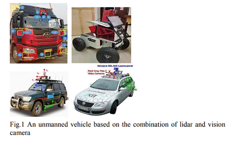
Ground unmanned platforms, represented by unmanned vehicles and robots, have broad application prospects in reconnaissance, safety inspections, and explosion-proof tasks due to their autonomy, flexibility, and small size. In recent years, there have been many studies on environmental perception and scene understanding of unmanned platforms. Among many key technologies, obtaining target pose information is a key prerequisite for unmanned platforms to achieve target perception and environmental scene understanding, as shown in Figure 1.
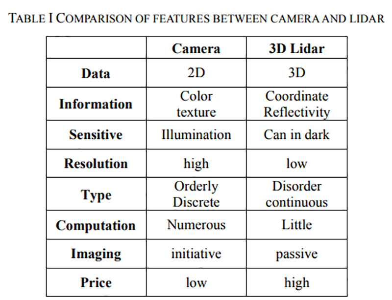
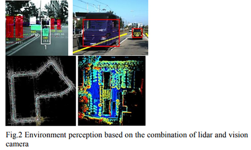
At present, most unmanned platforms adopt a "LiDAR+visual camera" solution to achieve complete environmental perception. Among them, LiDAR obtains high-precision and discrete 3D point cloud data on the target surface, which is less affected by the environment and has good robustness; Visual cameras can obtain high-resolution and high-quality two-dimensional visual information, which has great advantages in environmental perception and object detection. Due to the high complementarity of information between cameras and LiDAR, fusion of the two can not only overcome the shortcomings of a single sensor in environmental perception, but also obtain richer target observation data, improving the accuracy of its environmental perception, as shown in Figure 2 and Table I.
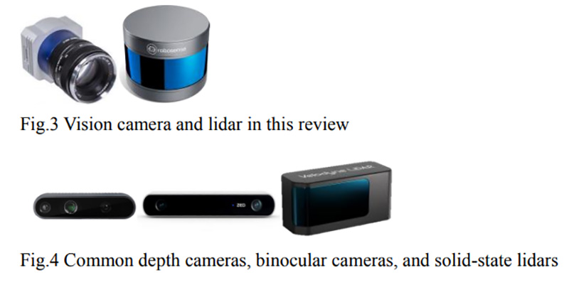
Due to the sparse data points of LiDAR and the high resolution of visual cameras, the joint calibration of LiDAR and visual cameras is the fundamental link to achieve their fusion. In response to the joint calibration of LiDAR and visual cameras, various calibration methods have been proposed. However, most of these methods are based on actual needs, so there is no systematic solution, and there is a lack of open source calibration datasets. Various methods are also not unified, making it difficult to provide clear references for researchers. On this basis, this article summarizes the advanced calibration methods for joint calibration of LiDAR and single camera in recent years. This article will focus on the basic issues of constructing a joint calibration system, designing calibration boards, and solving calibration parameters, as shown in Figures 3 and 4.
Construction of calibration system
A typical calibration system can be divided into the following steps: first, select the LiDAR, visual camera, and calibration board according to the requirements, then establish the conversion relationship of the calibration target in different coordinate systems according to certain methods, and finally solve the conversion matrix. Among them, the selection of calibration plates, the establishment of coordinate system conversion relationships, and the solution of calibration equations are key links.
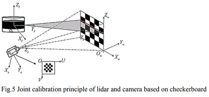
Figure 5 shows the four main coordinate systems involved in the joint calibration of LiDAR and camera based on calibration boards! Pixel coordinate system (u, v), camera coordinate system, image plane coordinate system (x, y), LiDAR coordinate system.
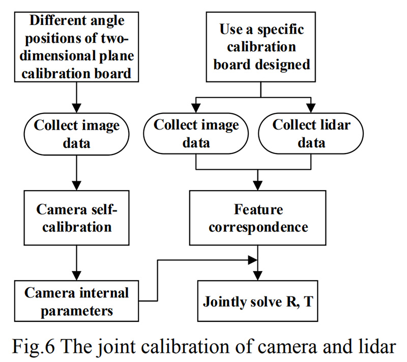
The joint calibration of cameras and LiDARs usually includes two parts: internal parameter calibration and external parameter calibration. Internal parameter calibration mainly solves the distortion of the camera CCD sensor itself and the impact of installation; External parameter calibration is mainly used to establish coordinate transformation equations between two sensors. As shown in Figure 6, this is the flowchart of the joint calibration of the camera and LiDAR!
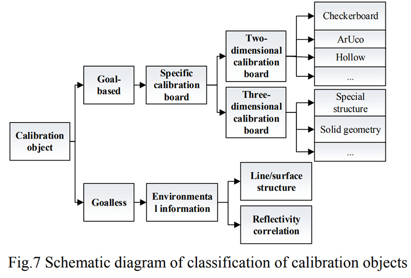
The selection of calibration boards varies depending on the calibration object and the extracted feature points, and calibration can be carried out in two ways: target based calibration or no target calibration. Target based calibration typically uses specific calibration boards to facilitate algorithm extraction of specific feature points, while non target calibration methods typically directly use material or structural features from the environment to extract and match for calibration, increasing the range and convenience of calibration, as shown in Figure 7.
1)Target-based Calibration
The characteristic of target based calibration is to use a specific form of calibration board during the calibration process. In this way, feature points are easy to capture, the required algorithm is simple, and the computational power is small. But the drawbacks are also obvious: firstly, the sensor must be calibrated before use, and real-time calibration cannot be performed. Another is that two-dimensional flat panels (such as chessboards) need to obtain clear correspondence, which not only makes the final calibration accuracy heavily dependent on 3D and 2D feature points, but also requires manual intervention!
2D calibration board
A two-dimensional calibration board typically depends on a specific calibration target, with the most commonly used being a chessboard. Zhang [1] first proposed a chessboard calibration board that estimates the parameters between a two-dimensional LiDAR and a camera through a chessboard with multiple poses. Ranjith Unnikrishnan et al. [2] proposed a calibration method for 3D LiDAR and camera external parameters based on Zhang's proposed camera and 2D LiDAR calibration method, as shown in Figure 8.
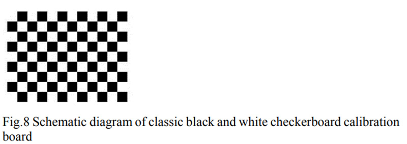
However, due to the large distance between the longitudinal beams of LiDAR and the low acquisition resolution, it is difficult to ensure the accuracy of precise vertices through edge extraction. Lyu [3] manually adjusts the position of the chessboard in the laser point cloud so that the scanning line can scan to the vertices of the chessboard, but this will increase the time and complexity of the calibration process.
In order to solve the problem of inaccurate edge fitting of point clouds, Kang Guohua et al. [4] used coarse registration of point cloud centers to achieve overall fine registration of point clouds. From another perspective, in addition to outputting coordinate information of 3D point clouds, LiDAR can also bring back reflection intensity information. [5] A threshold was set for the laser radar reflection intensity of different materials to obtain a laser radar point cloud, and a new calibration board was designed based on this.
The ArUco tag is a special encoding mode that facilitates the detection and correction of errors in the tag itself. Hall et al. proposed a calibration board for an experimental setup composed of multiple units. Method [6] uses ArUco markers to calculate the corner points of the calibration plate in the camera coordinate system, extracts the fitted edge lines from the LiDAR points, and then calculates the external parameters of the LiDAR camera. In practical applications, this method, like LiDAR in chessboards, includes unstable edge extraction and line fitting algorithms, which will bring significant errors to calibration. In addition, due to the need for multiple calibration boards, this method is more complex. In order to increase the extractable features of the LiDAR point cloud, a hollow calibration board has emerged. The work of Dong et al. [7] and Zhu et al. [8] is somewhat similar. They constructed a hollow circular hole at the center of a black and white chessboard and calibrated the center of the hole as a feature point. However, due to the lack of obvious features in the LiDAR point cloud, the coordinates of the center can only be approximately calculated from the entire circular hole point cloud, as shown in Figure 9.
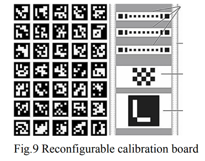
Recently, Huang Qiang et al. [9] proposed a joint calibration method for LiDAR and visual sensors based on a reconfigurable calibration board, which uses a barcode like method to automatically recognize the feature points of LiDAR and adds a camera verification mechanism to alleviate errors caused by unstable camera recognition during the calibration process.
3D calibration board
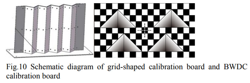
The purpose of the 3D calibration board is to better assist the LiDAR in finding feature points, thereby better matching feature points. When the background is impure, the hollow flat panel mentioned in the previous section may cause pixel mixing. Zhou Shihui et al. [10] analyzed the mixed pixel error caused by the flat hollow calibration board, designed a special grid shaped calibration board, and based on the feature point matching method, achieved high-precision joint calibration of industrial cameras and LiDAR to achieve pixel level image fusion effect. Cai Huaiyu et al. [11] designed a calibration board (BWDC) with gradient depth information, planar angle information, and position information. This method not only extracts features from one dimension, but also effectively utilizes the ability of LiDAR to extract three-dimensional information. However, this places high demands on the design and manufacturing accuracy of calibration boards, increasing costs and errors. As shown in Figure 10.
Pusztai et al. [12] used a box with three vertical edges as the calibration object, estimated the 3D vertices of the box by extracting its edges, and matched them with the 2D vertices extracted from the image. This method is universal as it can be used for ordinary boxes. Similarly, Xiaojin Gong et al. [13] proposed external calibration of 3D LiDAR cameras based on arbitrary trihedra. Due to the fact that the trihedral targets used for calibration can be orthogonal or non orthogonal, which typically occurs in structured environments, it has a wide range of applications.
2)Targetless Calibration
Non target calibration does not require manual calibration of targets, making online calibration more convenient, but with low accuracy and poor robustness. For example, when encountering situations that require online calibration, the relative position of the fixed sensor may change due to mechanical vibration, and its calibration parameters may become inaccurate over time. Due to the extreme sensitivity of most fusion methods to calibration errors, their performance and reliability are severely compromised. In addition, most calibration processes require starting from scratch, so manually updating calibration parameters continuously is both cumbersome and impractical. In order to overcome the limitations of calibration boards and achieve online calibration through natural scenes, researchers have conducted extensive research!
Some of these methods use the correlation between RGB texture and LiDAR reflectance, while others extract edge or line features from images and laser point clouds for correlation measurement [17]. Castorena et al. [19] used natural alignment of depth and intensity edges combined with Gaussian mixture models for calibration and obtained an automatic, goalless, and fully data-driven global matching optimization method. These methods require relatively accurate initial parameters, otherwise they are prone to getting stuck in local extremes. Therefore, target free calibration methods used for self recognition scenes are usually used to fine tune external parameters. There are also some trajectory registration based on odometry [20], registration of dense point clouds and laser point clouds for time-series visual frames [21], and even deep learning based methods [22], [23]. These methods are not only highly dependent on the environment, but also influenced by the accuracy of vision or laser odometry. The current technology has low accuracy and is not universal, requiring further research and development.
3) Establishing calibration equations
In the process of camera sensor acquisition, in order to determine the relationship between the three-dimensional geometric position of points on the surface of a spatial object and their corresponding points in the image, a geometric model of camera imaging must be established.
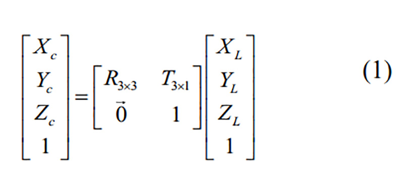
(1) 3D coordinate conversion: The conversion from camera coordinate system to LiDAR coordinate system is as follows:
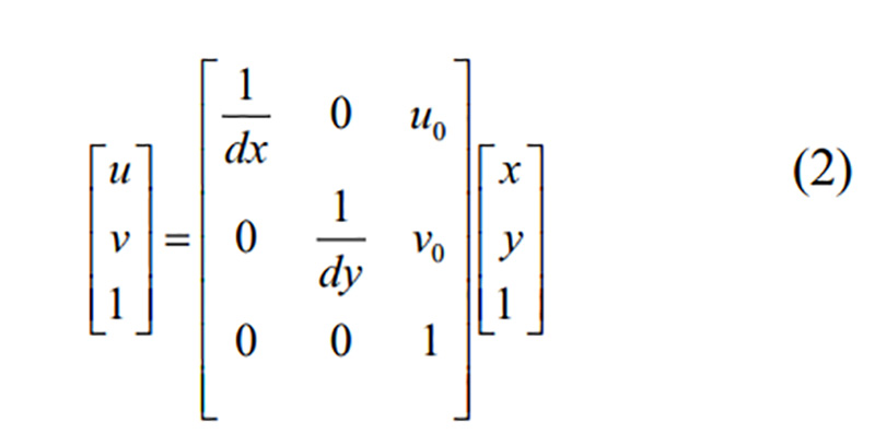
(2) 2D coordinate conversion: The conversion from pixel coordinate system to image coordinate system is as follows:
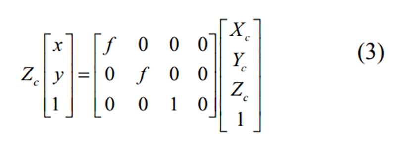
(3) Coordinate conversion based on pinhole imaging principle: The conversion from camera coordinate system to image coordinate system is as follows:
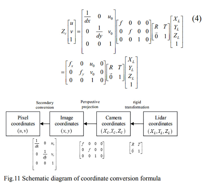
(4) Merge conversion: The conversion from LiDAR coordinate system to pixel coordinate system is combined and derived as shown in Figure 11, with the following formula:
Parameter solving
1) Camera reference
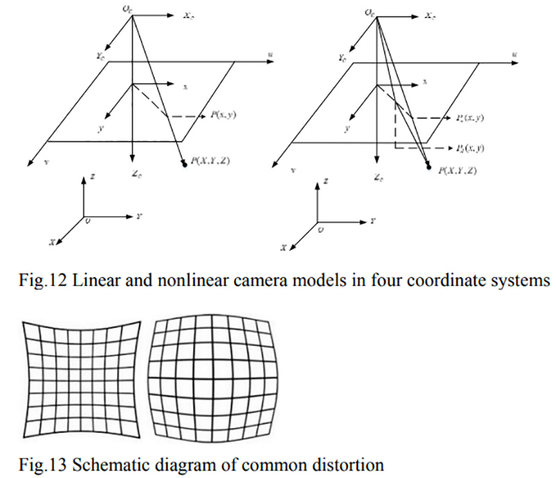
To simplify the calculation, a linear ideal pinhole camera was assumed, as shown in Figure 12. However, in reality, due to deviations in camera lens accuracy and assembly process, camera imaging inevitably introduces distortion. The distortion of real images and two common camera images is shown in Figure 13, resulting in image distortion, as shown in b in Figure 12.
Internal parameters are one of the important calibration parameters for visual measurement, which reflect the precise correspondence between spatial points and imaging points in computer image coordinates, as shown in Figure 14.
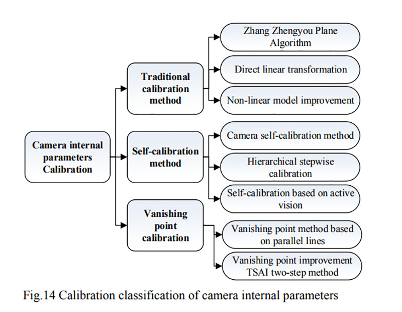
Traditional camera calibration methods. Traditional camera calibration methods use calibration targets or three-dimensional calibration fields with known structures and high accuracy as spatial reference objects. After establishing the world coordinate system, the spatial coordinates of each feature point were obtained. Based on the correspondence between the spatial points and image points, constraints on the internal parameters of the camera were established. Finally, by optimizing the algorithm to obtain internal parameters, the most widely used method for calculating camera internal parameters is the Zhang Zhengyou method [24]. Inspired by Zhang Zhengyou's method, many open-source library functions, such as OpenCV, ROS, Matlab, and some toolboxes [25] [26], use this method for development and calibration!
Camera self calibration method. The camera self calibration method refers to the process of establishing corresponding relationships using a set of images containing overlapping scenes captured by the camera, and completing geometric calibration without relying on calibration reference objects. Due to only using its own constraints, it is independent of the relative motion state between the camera and the surrounding environment. It has higher flexibility and is suitable for situations where calibration targets cannot be used due to harsh conditions. A camera self calibration method using the characteristics of absolute quadratic curves and polar transformations to solve the Kruppa equation [27], [28], [29]. This method of directly solving the Kruppa equation optimizes too many parameters during the solving process, making it easy to fall into local optima. When the image noise is large, the calibration accuracy will decrease and the robustness will deteriorate. Instead, a layered and step-by-step calibration method is used. It uses projection calibration as the basis, selects a certain image as the standard, and performs projection alignment to reduce unknowns. Then use nonlinear optimization algorithms to solve all unknown problems [30]. Another branch is camera self calibration technology based on active vision, where the active vision system precisely installs the camera on a controllable platform. Actively controlling the camera to complete photo shooting according to the specified motion trajectory, and finally using the camera's motion parameters to determine internal parameters [31], [32], its drawbacks are higher requirements for experimental equipment, greater limitations on model parameters, and poor noise resistance.
A method based on vanishing point calibration. Since the 1990s, a large number of scholars at home and abroad have begun to study methods based on vanishing point calibration. Geometrically, the vanishing point of a world line is obtained by the intersection of rays parallel to the line and passing through the camera center and image plane. Therefore, the vanishing point only depends on the direction of the line and is independent of its specific position [33], [34], [35]. The vanishing point calibration method does not require object control points, but uses the constraint relationship between the camera's own parameters to establish the model. This greatly improves the flexibility of calibration, achieves real-time online calibration, and has a wide range of applications. Its drawbacks are poor robustness and low accuracy, as in most methods based on vanishing point calibration, the azimuth elements in the camera are calibrated through the vanishing points of a single image, while traditional vanishing point calibration algorithms require three sets of parallel lines that are orthogonal to each other in the scene. However, due to factors such as noise, it is often limited in practical applications. The internal parameters and distortion parameters of a camera are inherent parameters and are usually fixed after leaving the factory. Therefore, many manufacturers now directly provide the internal factory parameters of the camera. Meanwhile, with the internal optimization of camera design, its distortion control is getting better and better. This is also the reason for the slow research and update of internal parameter calibration algorithms!
2) External parameter solving
From the perspective of data selection methods, it can be divided into manual calibration solutions and automatic calibration solutions. Manual calibration was the first calibration method developed and used in the early days, and it is loved by calibration personnel for its simple and effective operation and high accuracy. However, with the development of science and technology, the huge amount of data in images and point clouds has led to a sharp increase in labor costs. A single manual calibration can no longer meet people's needs for speed, automation, and robustness. Automatic calibration has emerged, as shown in Figure 15. The external parameters of the camera in LiDAR are calibrated according to different principles!

Manual external parameter calibration
For camera LiDAR external parameter calibration, the calibration object can provide accurate geometric dimension information, and manual operation can provide accurate matching information. The most commonly used method is to use a chessboard to determine a series of 3D point pairs for calibration. For example, Dhall et al. [36] manually selected 3D points and used the least squares method to solve the problem, while Scaramuzza et al. [37] proposed a fast calibration method that does not rely on the calibration object, but is based on point features. The author manually selects a series of corresponding points with discontinuous depths from camera images and LiDAR point clouds to solve the problem. There are multiple calibration methods for manual camera LiDAR. Different methods have achieved high accuracy in different specific application scenarios. For systems that require real-time online calibration, the main problem with manual calibration is excessive reliance on manual operation and special calibration objects, which seriously reduces autonomy and intelligence.
Automatic external parameter calibration
With the urgent demand for intelligent applications, a large number of automatic calibration methods for external parameters of cameras and LiDAR have emerged in the past decade. These methods are divided into feature matching based methods, mutual information based methods, motion based methods, and deep learning based methods.
a) Calibration method based on feature matching
The method based on feature matching selects feature points and obtains the coordinates of feature points in the above two systems based on calibration boards. Based on feature matching, the conversion relationship between the LiDAR coordinate system and the camera pixel coordinate system is directly obtained. Then, the conversion matrix and internal and external parameters are calculated by solving the calibration matrix conversion process or using supervised learning methods. Currently, the feature matching methods based on LiDAR point cloud edge extraction mainly include indirect method and direct method.
Indirect method: Most methods convert LiDAR points into images and then perform edge extraction. Wang et al. [39] used the Canny algorithm to extract edges from images and generated distance images from 3D LiDAR point clouds using a boundary detector, establishing a correspondence between point cloud data and distance images. Merge 2D images and 3D point cloud data through pixel correspondence to obtain edge images with 3D information. Usually, the resolution of the camera and the point cloud are different, and this method may introduce some errors.
Direct method: In an image, areas where grayscale values suddenly change form the edges of the image, and this change is called image gradient. Based on the features of image edges, Xia et al. [40] proposed the concept of 3D point cloud gradient, and then developed a LiDAR point cloud for fast edge extraction. This fitting method can extract more edge features, has high accuracy, and is not sensitive to the density of points.
b) Calibration method based on mutual information
The main idea of mutual information based methods is to find relevant variables in camera images and LiDAR point clouds. By calculating the mutual information between the grayscale value of the camera image and related variables (such as the reflectivity or angle of the lidar reflection), and then maximizing the mutual information to optimize the calibration of external parameters. Pandney et al. [41] believe that there is a strong correlation between the reflectivity of LiDAR point clouds and the grayscale values of camera images, and the probability of reflectivity and grayscale values is calculated using kernel density estimation methods. Finally, mutual information is calculated and external parameters are optimized using the Barzilai Borwein steepest descent method. Taylor et al. [42] argue that the angle between the normal of the 3D point corresponding to the camera image point and the camera will affect the reflection intensity. Calibration is performed by calculating the reflectivity of the LiDAR point cloud and the mutual information between the above angles corresponding to the camera image point. It can be seen that when two sensors perform tight data fusion, precise external parameters between the two sensors are particularly important. Due to the sparsity of the LiDAR point cloud, it is not possible to directly extract scattered LiDAR points at the corners of the calibration plate, which will result in greater errors and precise corner calculations. Therefore, the external calibration method of LiDAR camera based on directly extracted reflection intensity feature points can effectively compensate for this problem. However, the effectiveness of mutual information based methods is related to the material and reflectivity of the target object in the environment where the sensor is located, and is susceptible to interference from factors such as lighting conditions and weather changes.
c) Motion based calibration method
Motion based methods typically solve external parameters from continuous motion data or multi view data. Firstly, calculate the motion of the camera and LiDAR separately, and then solve the direct external parameters of the camera and LiDAR through hand eye calibration. Taylor et al. proposed a calibration method that can be applied to any system composed of LiDAR, camera, and navigation sensors. The author first registers the consecutive frames of each sensor and then uses connections to calibrate external parameters. Ishikawa et al. [44] used a KLT tracker to track the projection points of the LiDAR on the image plane, and continuously optimized the translation vector lacking 3D scale through projection errors, achieving more accurate results than Taylor's. Zhao [45] used the front and back frame images of the camera to reconstruct the 3D urban scene and calculate the pose changes, and calculated the front and back frame ICP of the LiDAR point cloud to obtain the spatial changes of the point cloud. Meanwhile, many studies have achieved image registration on unmanned aerial vehicles and LiDAR point clouds through techniques such as keyframes and motion recovery structures. For example, Nedevsci et al. [46] used feature matching to detect sensor offset during vehicle driving. This method finds the edges in the image by performing distance transformation on the image, while converting the LiDAR point cloud into a distance image. Establish an objective function based on edge information. This method can eliminate drift generated during vehicle movement and automatically adjust external parameters.
It can be seen that motion based methods are suitable for solving calibration parameters and initial values for large-scale scenes. However, the main drawback of motion based methods is that the motion of a monocular camera lacks 3D scale information, and there is a significant error between attitude estimation and the data itself, requiring accuracy breakthroughs. Due to the ability to recover the proportion problem through stereo vision, the calibration problem is greatly simplified, making this method more suitable for stereo cameras.
d) Calibration method based on deep learning
With the rapid development of deep learning in recent years. Various perception tasks in autonomous driving can be achieved and performed well through deep learning, and external parameter calibration of LiDAR and cameras can also be predicted through neural networks. Schneider et al. proposed the first method of applying deep learning to calibration problems, which extracts camera images and LiDAR point clouds using RegNet neural networks, and then performs regression. Ganesh Iyer and others designed a geometrically supervised deep network that can automatically estimate the 6-DoF rigid body transformation between 3D LiDAR and 2D cameras in real-time. Among them, CalibNet reduces the need for calibration targets, greatly saving calibration work. Recently, Kaiwen Yuan et al. [49] proposed a LiDAR camera calibration method based on RGGNet. This method considers Riemannian geometry and uses deep generative models to learn implicit tolerance models. This method considers both calibration errors and tolerances within the error range, achieving good calibration results. For deep neural networks, there is no need to pre extract features from images and LiDAR point clouds to establish a mapping and connection between the two data. On the contrary, it is directly handed over to nodes in the neural network to find potential relationships. For calibration problems, supervised learning is clearly not enough. It is difficult to directly obtain the true values of external parameters, and it is also difficult to provide a reliable and observable training set. Therefore, unsupervised or semi supervised learning is more suitable for external parameter calibration problems. However, existing algorithms require higher usage conditions, a large amount of training requires huge computational resources, and generalization ability urgently needs to be improved.