Create calibration data model
You can create a calibration data model using the operator create.calib_data, specifying the number of cameras and calibration objects. When using a camera, you also use a separate calibration object.
Then, what you need to do is:

Specify the initial values of camera internal parameters
Describe the calibration object
Specify the initial value of camera intrinsic parameters
You can set the camera's internal parameters using the operator set_calib_data_cam_param.
In addition to calibrating the data model, the operator also requires the following parameters as inputs:
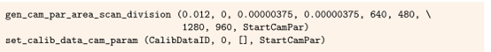
CameraIdx: Index of the camera (0 represents a single camera)
CameraType: The type of camera
CameraParam: A tuple of the initial value of camera intrinsic parameters
That kind of distorted model to use
For array cameras, two distortion models are available: partition model and polynomial model. The partition model uses one parameter to construct radial distortion, while the polynomial model uses five parameters to construct radial and centrifugal distortion.
The advantage of partitioning models is that distortions can be quickly applied, especially for reverse distortions, such as if world coordinates are mapped to the image plane. Moreover, if only a few calibration images are used or the field of view coverage is insufficient, the partitioning model will obtain more stable results than the polynomial model. The main advantage of polynomial models is that they can construct distortions more accurately, as they use higher-order terms to construct radial distortions, and they also construct centrifugal distortions. It should be noted that polynomial models cannot be extrapolated. Therefore, reverse distortion must be iteratively calculated, which is slower than the calculation of reverse distortion in partition models.
Generally, partition models should be used for calibration. If the calibration accuracy is not high, a polynomial model can be used. However, it should be noted that the calibration sequence used for polynomial models must provide a complete coverage area, which is later used for measurement. Distortion may be inaccurately constructed outside the area not covered by the calibration board. This situation occurs at the edge of the image and also within the field of view area that is not covered by the calibration board.
Describe the calibration object
By using the operator set_calib_data_calib_object, you can specify the information required to calibrate the object.
If you are using a HALCON calibration board, the corresponding description file name is sufficient.

How to obtain a suitable calibration board
The simplest way to determine the camera parameters for a CCD camera is to use the HALCON calibration board (as shown in Figure 1). In this case, the entire process of finding the calibration handle, extracting calibration marker points, and determining the correspondence between the extracted calibration marker points and their respective 3D world coordinates can all be automatically executed. More importantly, the calibration board is more precise, with a size of 1um or smaller, which is a prerequisite for high-precision applications.
Two types of HALCON calibration boards are supported. Especially, calibration boards for hexagonal and rectangular arrangement of marker points are feasible. The calibration board with hexagonal arrangement was introduced in HALCON 12 and is recommended for use in most applications because it provides the following advantages compared to the calibration board with rectangular arrangement of marker points:
A calibration board with rectangular arrangement of marker points should fill a quarter of the image field of view. In order to cover the entire field of view, including different tilts, many images (at least 10 to 20) are required. Because the hexagonal calibration board contains a large number of landmark points, a single image can cover the entire image area, and fewer images (6 to 7) are needed to obtain comparable calibration results.
2. The calibration board for rectangular arrangement of marker points must be visible throughout the image, while the calibration board for hexagonal arrangement can extend beyond the edge of the image. Furthermore, when placing the calibration board, the latter does not require much attention. The acquisition of calibration board images becomes faster and more convenient without any loss of stability.
A hexagonal calibration board should fill the entire image area on a single image. A rectangular calibration board should cover at least one ninth of the image area. To improve the quality of calibration, we recommend a calibration board that covers at least a quarter of the image area.
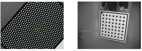
Figure 1: HALCON calibration plates of different materials and sizes: (a) hexagonal arrangement of marking points (b) rectangular arrangement of marking points
Use your own calibration object
With HALCON, you are not limited to using a flat calibration board, such as the HALCON calibration board. You can use a 3D calibration board or even any feature point (natural marker). The only requirement is that the 3D world position of the model points is known and has high accuracy.
Then, you simply pass the 3D coordinates of all points (marker points) of the calibrated object as a tuple to the CalibObjeDescr operator set_calib_data_calib_object. The x, y, and z coordinates of all points must be packed in the order of [x, y, z] tuples.
However, the main thing to note is that if you use your own calibration object, you cannot use find_calid_object anymore. On the contrary, you must determine the 2D position of the model points and their corresponding relationship with the 3D points on your own.
Observing calibration objects in multiple poses
The main input data for calibration is what is called observation. Therefore, the calibration object is placed in different positions. For each pose, the camera captures an image. On this image, the landmark points of the calibration object are extracted, along with their (pixel) coordinates, as well as the camera index, calibration object, calibration object pose, and the index containing the response landmark points, all of which are stored in the calibration data model.
If you use a standard HALCON calibration board, you can use the operator find_calid_object to extract coordinates, which will automatically store the obtained information into the calibration data model, including the coordinates of the landmark points and the corresponding list of landmark points.
If you are using your own calibration object, you must extract its marker points and determine their corresponding relationships, and then store the information in the calibration data model using set_calib_data-observ_points.
Rules for obtaining calibration images
If you want to obtain accurate results, please follow the following rules:
1. Use a clean calibration board
2. Cover the entire field of view with multiple images, for example, place calibration at least once in all areas of the field of view
3. Change the direction of the calibration board, including its rotation around the x-axis and y-axis, so that the perspective distortion of the calibration pattern is clearly visible. Without some tilted calibration plates, the focal length cannot be reasonably calculated (a tilt angle close to 45 degrees is recommended)
4. For hexagonal calibration plates, use at least 6 images, and for rectangular calibration plates, use 10 to 15 images
5. For rectangular calibration boards, use a darker background light than the calibration board for illumination
6. Calibrate the grayscale value of the bright part to at least 100
7. The brightness contrast of the calibration board should exceed 100
8. Use a light that evenly illuminates the calibration board
9. The image cannot be overexposed (the bright parts of the image should be strictly below 255)
10. The diameter of the circle should be at least 20 pixels
11. The diameter of the circle should have at least 20 pixels in pixels
12. For the selection of calibration board size, hexagonal calibration boards should cover the entire image, while rectangular calibration boards should cover at least 1/4 of the entire image
13. A calibration plate arranged in a hexagonal pattern, where at least one positioning image is fully visible in the image. If at least two positioning maps are visible, it is possible to check if the calibration board is reflective. For the calibration of rectangular arrangements, the calibration should be fully visible in the image.
14. The image should contain as much noise as possible
15. Images should be strictly focused, for example, transitions between objects should be clearly defined.
It should be noted that a good calibration result can only be obtained when the calibration markers are uniformly distributed in the camera's field of view. You can imagine a portion of the 3D space relative to the field of view as a calibration volume, as shown in Figure 2, which shows the two poses of the calibration board and the positions of their calibration markers when viewed from different angles. It can be seen, for example, from face 1, that a larger part is not covered by the marker points. In order to obtain a more uniform distribution of landmark points and obtain a good calibration result, you must place calibration boards in your other images, so that the empty part of the calibration volume is minimized for the entire perspective. Note that when there is a very small calibration board (compared to the field of view), this means that more calibration images than recommended are needed.
If an image is used in the calibration process or if the direction of the calibration board does not change in different calibration images, it is impossible to determine the focal length and camera pose well; In this case, only the ratio between focuses and the distance between the calibration board and the camera are determined. However, it is possible to measure world coordinates on the calibration board plane, but it is not possible to adapt camera parameters to measurements on another surface, such as the surface where the calibration board is placed.
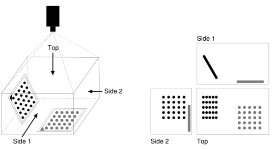
Figure 2: View of calibration volume: (left) Calibration volume with two calibration poses and (right) Distribution of calibration landmark points when viewed from different angles. For a good calibration result, the area without calibration markers (especially from the perspective of face 1, which is larger) must be minimized through careful selection of more calibration board poses.
The accuracy of world coordinates depends heavily on the number of images used in the calibration process, in addition to the measurement accuracy in the images. The more images (with significantly different calibration board poses) are used, the more accurate results will be obtained.
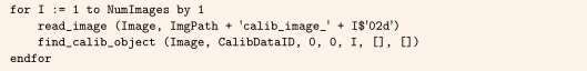
Extract the marker points on the HALCON calibration board
The operator find_calid_object searches for the calibration board, determines the image coordinates of the calibration marker points, and has high accuracy. Finally, the results are stored in the calibration data model.
It should be noted that find_caltab and find_marksAnd_pose are only used for rectangular alignment calibration boards. Also, they require complex parameter adjustments. On the contrary, it can be used for all standard HALCON calibration boards, automatically selecting appropriate parameters, making it easier to use.
Limit calibration to specific parameters
If the parameters of a certain camera are known, you can use the operator set_calib_data to exclude them from calibration. Similarly, you can limit calibration to certain parameters.
Perform calibration
After preparing the calibration data model, calibration can be performed by calling calibrate_cameras, using the calibration data model as input:

As a direct result, only calibration errors are returned. You can use the operator get_calib_data to further analyze the quality of calibration results.
The main calibration results, such as the camera's internal parameters, are stored in the calibration data model.
Accessing calibration results
The main result of the operator calibrate.camera is composed of the camera's internal parameters and the pose of each image calibration board. Operators store them in the calibration data model and can be accessed using the operator get_calib_data.

The camera extrinsic parameters cannot be directly obtained because the required world coordinate system information is not stored in the calibration data model. However, if the calibration board is directly placed on the measurement plane, its pose can be easily used to obtain the camera's extrinsic parameters, which are the pose of the measurement plane.
Determine camera external parameters
The camera extrinsic parameter describes the relationship between the measurement plane and the camera. For example, if only the extrinsic parameter is known, it is possible to convert the camera coordinate system (CCS) to the coordinate system of the measurement plane, and vice versa. In HALCON, the measurement plane is defined as the plane of the world coordinate system (WCS) z=0.
Camera extrinsic parameters can be determined using different methods:
1. Utilize the pose obtained from a calibration image, where the calibration plate is directly placed on the measurement plane. In this case, you can use the operator get_calib_data to obtain its pose.
2. Separate the determination of camera intrinsic parameters from the determination of camera extrinsic parameters by placing an additional image directly on the measurement plane through a calibration board. Apply find_calib_object to extract calibration landmarks and poses.
3. Determine the corresponding relationship between 3D world points and their image mapping, and then call vector_to_pose.
If you only need to accurately measure the size of an object, rather than the absolute position of the object in a given coordinate system, one of the first two methods can be used.
The latter two cases have the advantage that the decision of camera extrinsic parameters does not rely on camera intrinsic parameters. If a single camera is used to measure on multiple planes, or if the camera cannot be calibrated in place, this will be more flexible and useful.
Below, we will provide a detailed explanation of different situations.
Place the calibration board on the measurement plane in one of the calibration images
The first scenario is the easiest way to determine external parameters. The calibration board must be placed directly on the measurement plane, such as on an assembly line.
Because the pose of the calibration board can be determined through the operator calibrate_cameras, you can easily access its pose through the operator get_calib_data. In this way, with a single calibration step, the internal and external parameters can be determined. Here, the pose of the calibration plate (calibration object index 0) is determined in the first calibration image. Please note that each pose is composed of 7 values.

If the calibration is infinitely thin, the resulting pose will be the true pose of the measurement plane. Because the real calibration board has a thickness d>0, the position of the calibration board is moved by a quantity d perpendicular to the measurement plane, such as along the z-axis of WCS. To correct it, we need to move the pose d units along the z-axis of WCS. To perform this move, the operator set_origin_pose is utilized:

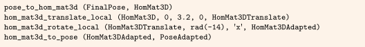
Generally, as long as the spatial relationship between the calibration board and the measurement plane is known, the calibration board can lock its direction arbitrarily in WCS (as shown in Figure 3). Then, in order to obtain the pose of the measurement plane from the calibration board pose, a rigid transformation is necessary. In the following example, the pose of the calibration board is translated along the y-axis and then rotated around the x-axis.
Place a calibration board on the measurement plane in a separate image
If the advantages of using the HALCON calibration board can be combined with the flexibility of separating camera internal and external parameters, the second method for determining camera external parameters can be used.
Firstly, the camera is calibrated according to the calibration steps. This can be done before the camera is installed at the final point of use.
Then, after installing the camera at the final point of use, the external parameters can be determined. All that is needed is to take a picture, where the calibration is directly placed on the measurement plane. From this diagram, the external parameters can be determined. Here, the internal reference and calibration board can be directly placed on the measurement plane, and the world coordinates of the calibration marker points can be read from the file.

Then, the calibration markers and the pose of the calibration board are extracted:

Finally, considering the thickness of the calibration board, the value of the camera pose origin is translated by units of the calibration board thickness.

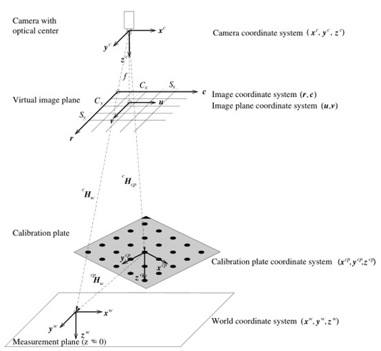
Figure 3 Relationship between calibration plate and measurement plane
It should be noted that if you want to divide the calibration step into two parts to complete, the focus of the camera is important because changing the focus is equivalent to changing the focal length, which is a part of the internal reference.
Utilize known 3D points and their corresponding image points
If it is necessary to perform measurements in a given world coordinate system, the third scenario can be used for determining external parameters. Here, you need to know the 3D world coordinates of at least three points on a straight line, and then you must determine the corresponding image coordinates of these points after mapping. Now, the operator vector to pose can be used to determine the extrinsic parameters of the camera.
The following program serves as an example of determining external parameters.
Firstly, the world coordinates of the three points are set.
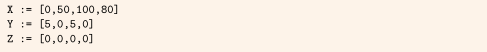
Then, the coordinates of the mapped points on the image are determined. In this example, they are simply set to some close values. In fact, they should be determined with sub-pixel accuracy because they define camera extrinsic parameters.

Finally, the operator vector to pose is called with known correspondence and camera intrinsic parameters.

Delete observation maps from the calibration data model
To determine the observation effect related to calibration, or to remove bad quality observation data from the calibration data model, the operator remove_calib_data_observer can be used to delete an observation graph.

When performing camera calibration again, it is important to pay attention to any changes in calibration errors.
Save results and destroy calibration data models
When accessing the results (or storing them using the operators writer_cam_par and write-pose), you can use the operator clear_calib_data to destroy the calibration data model.
Disclaimer: Part of the content is sourced from the internet and is for academic exchange purposes only. The copyright of the article belongs to the original author. If there are any issues, please contact for deletion.