Camera calibration can be said to be the foundation of computer vision/machine vision, but it is not easy for beginners to get started. This article will organize the logic of camera calibration for readers and answer the questions raised in the comments section at the end of the article. Divided into the following content:
The purpose and significance of camera calibration
Simplification and modeling of camera imaging process
Mathematical description of pinhole camera model
Calibrate the parameters of the pinhole camera model
The purpose and significance of camera calibration
The world we live in is three-dimensional, while photos are two-dimensional. This way, we can consider the camera as a function, with an input of a scene and an output of a grayscale image. The function of this process from 3D to 2D is irreversible.
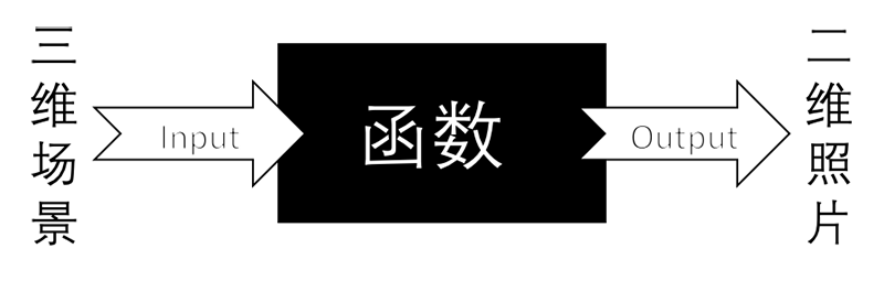
The goal of camera calibration is for us to find a suitable mathematical model and calculate its parameters, so that we can approximate the process from 3D to 2D and find the inverse function of the function in this process.
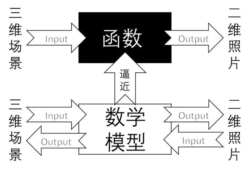
The process of approximation is called camera calibration. We use a simple mathematical model to express the complex imaging process and calculate the inverse process of imaging. After calibration, the camera can perform 3D scene reconstruction, namely depth perception, which is a major branch of computer vision.
Simplification and modeling of camera imaging process
When it comes to camera imaging, fundamentally speaking, it is discussing the lens of the camera. The fixed structure of the camera lens determines a pair of fixed object image conjugation relationships, known as "conjugation", which means that the object at a certain position in front of the lens must have its image at a certain position behind the lens, and this relationship is fixed. For example, objects at infinity will inevitably be imaged at the focal point of the lens. The fixed structure here refers to the fixed focal length and aperture of the lens.
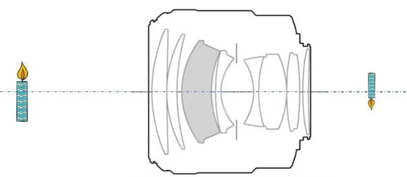
The above image shows Canon EF 85mm/F1.2L II USM. We can find a convex lens with the same object image conjugation relationship as this lens to equivalent it. We call this convex lens an equivalent lens and represent it with outward facing double arrows, as shown in the following figure.

The equivalence mentioned here only applies to the equivalence of the conjugate relationship between objects and images, that is, the equivalence of the optical path. The reason why lenses with different shapes are used in lenses is mainly to eliminate various aberrations and improve clarity. In other words, the purpose of equivalent lenses is not to replace lenses in practical applications (after all, a lens is expensive), but to help us understand. In this way, we can draw a clear sketch of the candle burning scene captured by the camera, as shown below.
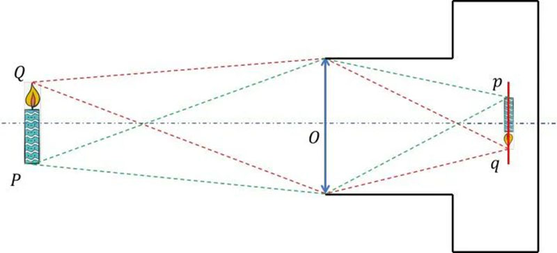
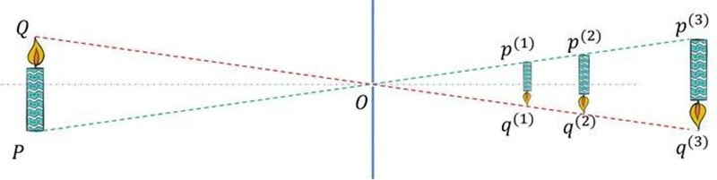
Among them, Q is the object point of the flame tip, q is the image point of the flame tip, P is the object point of the candle root, p is the image point of the candle root, O is the center of the equivalent lens (also known as the optical center), the red dashed line represents two imaging optical paths from object point Q to image point q, the green dashed line represents two imaging optical paths from object point P to image point p, and the red line represents the CCD surface.
Note that as we mentioned earlier, what we drew was a clear sketch of a candle burning scene captured by the camera. This indicates that the image points q and p happen to fall on the CCD surface. So, if the image points do not fall on the CCD surface, that is, the image captured by the CCD is not clear, how can we determine the position of the image points?
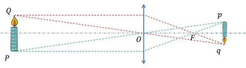
According to the drawing method of geometric optics, we can draw the positions of image points p and q from the light passing through the focal point F of the equivalent lens and the light passing through the optical center O. Now, we also use the drawing method for the sketch of a clear candle burning scene captured by the camera, only considering the object image relationship between Q and q.
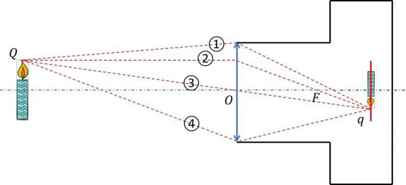
In this way, we can obtain four imaging optical paths: ① is the optical path passing through the upper edge of the lens, ④ is the optical path passing through the lower edge of the lens, ② is the optical path passing through the equivalent lens focus, and ③ is the optical path passing through the optical center. They all express the conjugate relationship between object point Q and image point Q. Obviously, the optical path passing through the optical center is the easiest to establish a mathematical model of the conjugate relationship between objects and images. Therefore, we use ③ to represent the imaging optical path and simplify the camera imaging process.
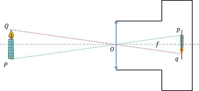
At this point, we have found that the simplified camera model and pinhole camera have similar imaging principles, so we refer to the simplified camera model as the pinhole camera model. The f in the above figure is the focal length of the pinhole camera model, but please note that the focal length of this pinhole camera is not the equivalent lens focal length. It only borrows the concept of "focal length" to converge light, expressing the distance from the CCD surface to the optical center.

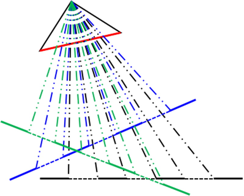
But what we are talking about is that the simplified camera model and the imaging principle of a pinhole camera are only similar and cannot be equated. As the principle of a pinhole camera is that light propagates along a straight line, real pinhole cameras do not have the concept of "focal length" or aberration, and their object image relationship does not have one-to-one correspondence, as shown in the following figure.
So, to be precise, simplifying the camera's imaging process into a pinhole camera model only borrows simple mathematical relationships from pinhole cameras to express some mathematical relationships that were originally difficult to express, greatly reducing complexity in mathematics. However, the cost of this simplification is also high. It does not consider aberration (although the pinhole camera model adds an anti distortion model), does not consider depth of field (the pinhole camera model does not have one-to-one correspondence between objects and images, believing that everything can always form a clear image), and assumes that the equivalent lens is a thin lens. So the pinhole camera model is just an approximation of the imaging process of a real camera, and we can even say that it is a very rough approximation. This makes the model more approximate to real cameras that are more in line with the pinhole camera model, such as network cameras, mobile phone lenses, monitoring probes, and so on.
Description of pinhole camera model
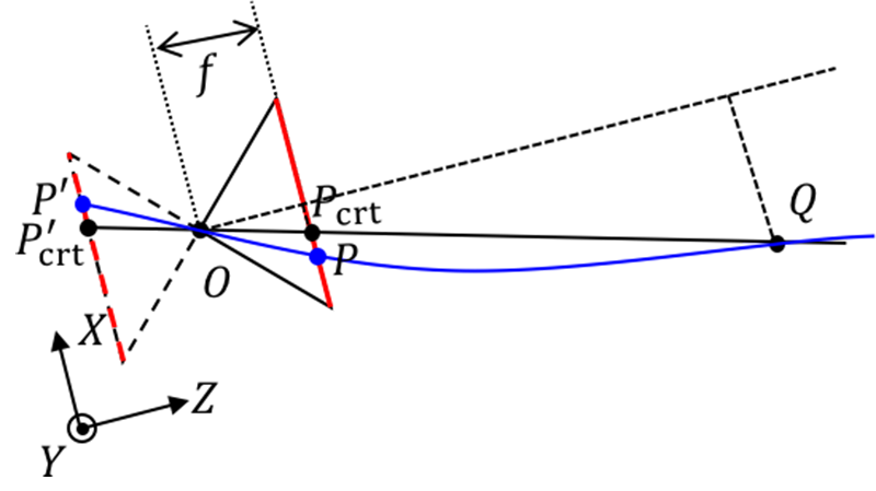
We simplified and modeled the camera imaging process to obtain a pinhole camera model, as shown in the following figure.

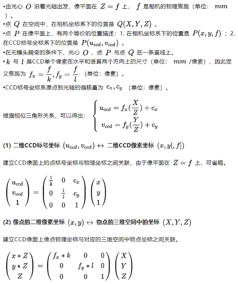
Firstly, establish a camera coordinate system. We take the optical center O as the origin of the coordinate system. The X and Y directions are the horizontal and vertical directions of the CCD pixel arrangement, and the Z direction is perpendicular to the CCD surface. We establish a right-hand coordinate system, which is a three-dimensional coordinate system. Secondly, we also need to establish a CCD labeling coordinate system: with the pixel labeling in the upper left corner of the CCD as the origin, the horizontal and vertical directions of the CCD pixel arrangement are U and V directions, which is a two-dimensional coordinate system. For the convenience of description, we will symmetrically flip the pinhole camera model over later, as shown in the following figure. From a mathematical perspective, they are equivalent.


Calibrate the parameters of the pinhole camera model

So in the calibration board, topological structures are printed, and the widely used ones are checkerboard and dot grids. The reason why these two become mainstream is not only because their topological structures are clear and uniform, but more importantly, the algorithm for detecting their topological structures is simple and effective. Checkerboard detection focuses on corner points, which can be obtained by calculating gradients in both horizontal and vertical directions of the captured chessboard image; The detection of dot grids only requires calculating the centroid of the captured dot grid pattern. If you develop a very perfect algorithm for detecting all facial features, you can use your photos as calibration boards.
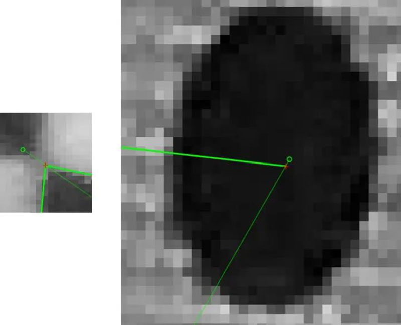
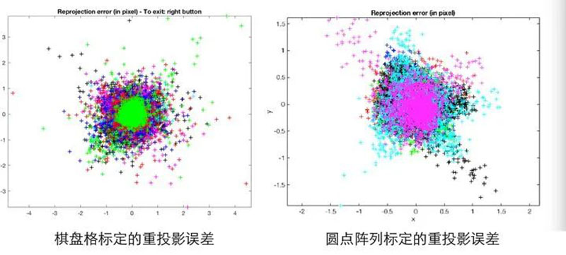
In my experience, the effect of a dot grid should be better than that of a chessboard grid, because the perspective invariance of the center of mass of the dots is much more stable than that of the corners of the chessboard grid. The following figure compares the errors of chessboards and circles of the same size and proportion at the maximum reprojection error. The red cross represents the extracted corner/centroid, and the green circle represents the corner/centroid position calculated by the pinhole camera model.
The following figure shows the reprojection error diagram of chessboard and dot grids, indicating that the error space of the reprojection error of dot grids is smaller.
However, the detection of dot grids seems to be Halcon's patent (questionable), so OpenCV and Matlab calibration toolboxes use chessboard grids, and if you want to use dot grids, you need to write your own algorithm. The calibration boards mentioned in the following text all refer to checkerboard patterns.
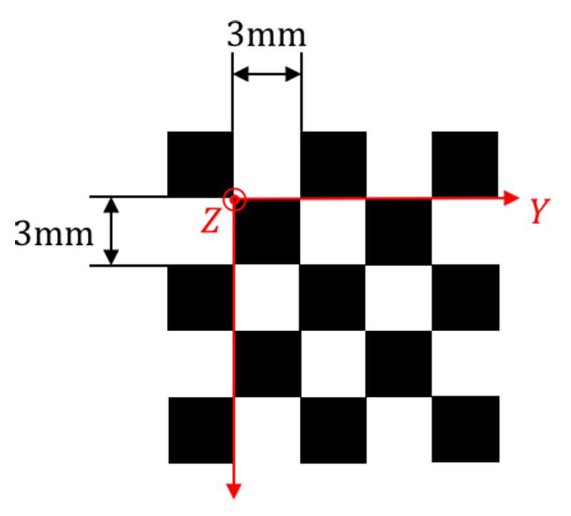
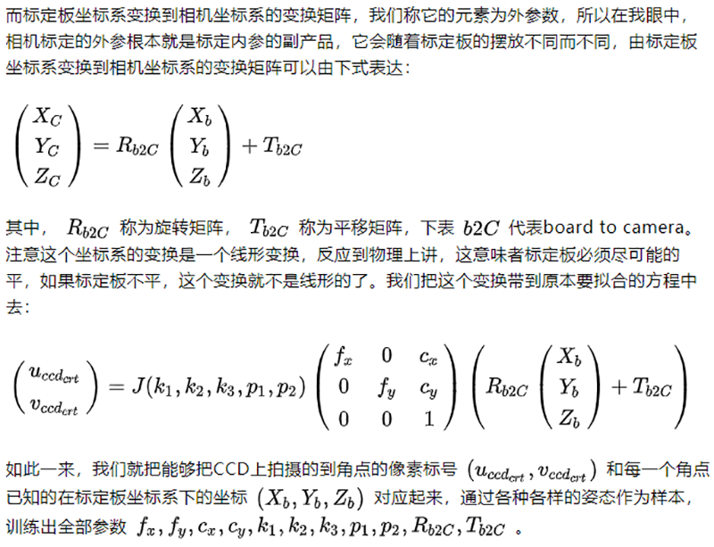
The second major function of the calibration board is to transform the corner points in the calibration board into the coordinates (X, Y, Z) in the camera coordinate system. For beginners in calibration, it is easy to overlook that the calibration board has a calibration board coordinate system. In other words, the position of each corner point in the calibration board coordinate system is determined and known.
As for the methods of parameter training, such as least squares, maximum likelihood estimation, etc., it is easy to find relevant information, which will not be repeated here. On Zhihu website, I recommend reading this article on how to solve calibration parameters. [Machine Vision] Zhang's Method Camera Calibration - Zhihu Column
If using the OpenCV or Matlab calibration toolbox for calibration, the physical dimensions of the chessboard grid need to be provided. This is actually establishing the coordinate system of the calibration board. From a measurement perspective, the accuracy of the calibration board is the benchmark for camera calibration accuracy and the first link in the error transmission chain. So in order to make the pinhole camera model closer to the real camera, there are the following requirements for the quality of the calibration board (in order of importance):
1. The flatness of the calibration board is high, and the chessboard is at right angles;
2. High consistency in the size of each grid on the calibration board;
3. The difference between the actual size and the nominal size is small.
Finally, pay tribute to our ancestor Zhang Zhengyou.
Transferred from: Zhihu
Author: Xu Xiangxiang (Ph.D. in Optical Engineering, Fudan University)
Link: https://zhuanlan.zhihu.com/p/30813733
Disclaimer: We respect originality, and the copyright of the cover and images in the text belongs to the original author. If there is any infringement of your rights, please contact us promptly to delete it