Camera calibration internal and external parameters
In the process of image measurement and machine vision applications, in order to determine the three-dimensional geometric position of a point on the surface of a spatial object and its corresponding point in the image, it is necessary to establish a geometric model for camera imaging, and these geometric model parameters are the camera parameters. Under most conditions, these parameters must be obtained through experiments and calculations, and the process of solving these parameters is called camera calibration (or camera calibration). Whether in image measurement or machine vision applications, camera parameter calibration is a crucial step. The accuracy of the calibration results and the stability of the algorithm directly affect the accuracy of the results produced by the camera. Proper camera calibration and improving calibration accuracy are prerequisites for subsequent work.
The geometric model parameters to be determined in camera calibration are divided into two types: internal parameters and external parameters. The function of camera internal parameters is to determine the projection relationship of the camera from three-dimensional space to two-dimensional images. The function of camera extrinsic parameters is to determine the relative positional relationship between camera coordinates and the world coordinate system.
The camera internal parameters have a total of 6 parameters (f, κ, Sx, Sy, Cx, Cy), where:
F is the focal length;
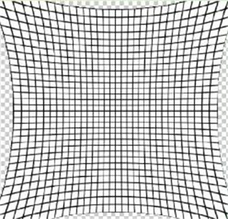
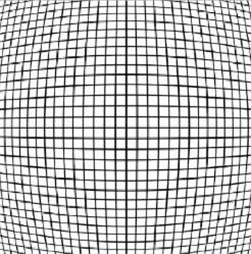
κ Represents the level of radial distortion, if κ If it is negative, the distortion is barrel shaped distortion. If it is positive, the distortion is pillow shaped distortion.
Sx, Sy is the scaling factor. In general, the camera imaging unit is not strictly rectangular, and its size in the horizontal and vertical directions is inconsistent, which leads to different scaling factors in the X and Y directions. Therefore, two scaling factors need to be defined separately. For a pinhole camera, it represents the distance between adjacent pixels in the horizontal and vertical directions on the image sensor;
Cx and Cy are the main points of the image, which are perpendicular to the intersection of the imaging plane and the image plane through the lens axis. For a pinhole camera, this point is the vertical projection of the projection center on the imaging plane, and also the center of radial distortion.
There are a total of 6 parameters for camera external parameters( α,β,γ, The relationship between camera coordinates and world coordinates (Tx, Ty, Tz) can be expressed as:
Pc= RPw + T
Where Pw is the world coordinate and Pc is the camera coordinate. In the formula, T=(Tx, Ty, Tz) is the translation vector, and R=R( α,β,γ) It is a rotation matrix, which represents the rotation angle around the z-axis of the camera coordinate system γ, The rotation angle around the y-axis is β, The rotation angle around the x-axis is α。 Composed of 6 parameters( α,β,γ, Tx, Ty, Tz) are camera extrinsic parameters.
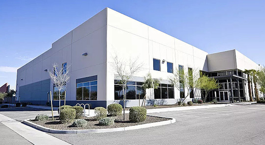
Usually, through the lens, an object in three-dimensional space is mapped into an inverted and reduced image, which is then perceived by imaging sensors.
In an ideal situation, the optical axis of the lens (which is a straight line perpendicular to the sensor plane through the center of the lens) should pass through the center of the image. However, in reality, due to installation accuracy issues, there is always an error, that is, the optical axis offset, which needs to be described using internal parameters;
In an ideal situation, the reduction ratio of the camera in the x and y directions is the same, but in reality, if the lens is not a perfect circle and the pixels on the sensor are not perfectly arranged in a tightly packed square, it may lead to inconsistent reduction ratios in these two directions. The internal parameter contains two parameters that can describe the scaling ratio in these two directions. It can not only convert the length measured by the number of pixels into the length measured by other units (such as meters) in three-dimensional space, but also represent the inconsistency of scale transformation in the x and y directions;
In an ideal scenario, the lens would also map a straight line in three-dimensional space into a straight line (i.e., a projective transformation), but in reality, the lens cannot be so perfect. After mapping through the lens, the straight line will bend, so the camera's distortion parameters are needed to describe this deformation effect. The following three types of distortions are pillow shaped distortion, barrel shaped distortion, and linear distortion.

The method of camera calibration
The camera calibration methods include traditional camera calibration, camera self calibration, and active vision camera calibration.
The traditional camera calibration method requires the use of a calibration object with known dimensions. By establishing the correspondence between the points on the calibration object with known coordinates and their image points, a certain algorithm is used to obtain the internal and external parameters of the camera model. According to the different calibration objects, they can be divided into three-dimensional calibration objects and planar calibration objects. The three-dimensional calibration object can be calibrated from a single image with high calibration accuracy, but the processing and maintenance of high-precision three-dimensional calibration objects are difficult. Planar calibration objects are easier to produce than three-dimensional calibration objects, and accuracy is easily guaranteed, but calibration must use two or more images. The traditional camera calibration method always requires calibration objects during the calibration process, and the production accuracy of calibration objects will affect the calibration results. At the same time, some situations are not suitable for placing calibration objects, which also limits the application of traditional camera calibration methods.
The advantage of traditional camera calibration methods is that they can be used for any camera model with high calibration accuracy. The disadvantage is that the calibration process is complex, requiring high-precision calibration templates, and in some cases, calibration blocks cannot be used.
The current self calibration algorithms mainly utilize the constraints of camera motion. The motion constraints of the camera are too strong, making it impractical in practice. The use of scene constraints mainly involves utilizing some parallel or orthogonal information in the scene. The intersection point of spatial parallel lines on the camera image plane is called vanishing point, which is a very important feature in projective geometry. Therefore, many scholars have studied camera self calibration methods based on vanishing points. The self calibration method has strong flexibility and can calibrate the camera online. However, due to its method based on absolute quadratic curves or surfaces, its algorithm robustness is poor. Relying solely on the correspondence between multiple images for calibration has the advantage of establishing only the correspondence between images, which is flexible and has a wide range of potential applications. However, the disadvantage is non-linear calibration and low robustness.
The camera calibration method based on active vision refers to calibrating the camera with certain motion information known to the camera. This method does not require calibration objects, but requires controlling the camera to perform certain special movements, which can be used to calculate the internal parameters of the camera. The advantage of camera calibration method based on active vision is that the algorithm is simple and can often obtain linear solutions, so it has high robustness. The disadvantage is that the system has high cost, expensive experimental equipment, high requirements for experimental conditions, and is not suitable for situations where motion parameter positions or cannot be controlled.
The premise of applying the active vision camera calibration method is that certain motion information of the camera is known. The advantage is that it can be solved linearly and has good robustness. The disadvantage is that it cannot be used in situations where the camera motion information is unknown and cannot be controlled.
Calibration template
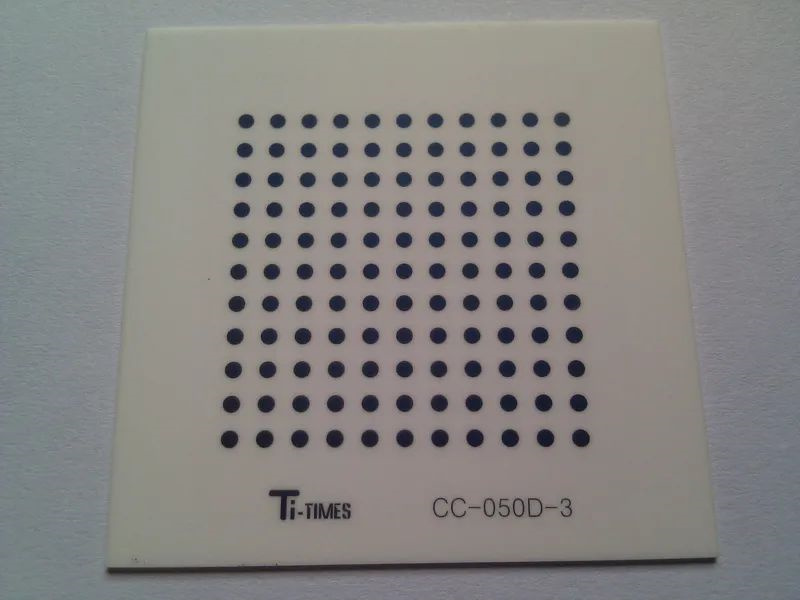
Calibration templates (calibration targets) are used in applications such as machine vision, image measurement, photogrammetry, and 3D reconstruction to correct lens distortion; Determine the conversion relationship between physical dimensions and pixels; To determine the three-dimensional geometric position of a point on the surface of a spatial object and its corresponding point in the image, it is necessary to establish a geometric model for camera imaging. By shooting a flat panel with a fixed spacing pattern array using a camera and performing calibration algorithms, the geometric model of the camera can be obtained, resulting in high-precision measurement and reconstruction results. The flat panel with a fixed spacing pattern array is the calibration template (calibration target).
Common types of calibration templates
1) Equal spacing solid circular array pattern Ti times CG-100-D
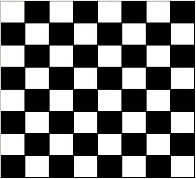
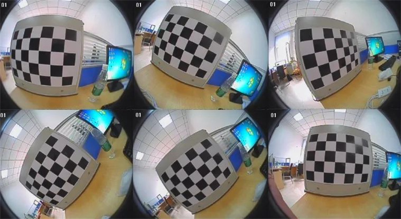
2) Chess board pattern Ti times CG-076-T
It usually requires 20 images, which is just an empirical value. In fact, too many are not good, and too few are not good. From a purely statistical perspective, the more images there are, the better. However, in reality, having too many images may worsen the results of parameter optimization, as there is an error in determining the coordinates of the checkerboard corner points, and it is difficult to say that this error conforms to a Gaussian distribution. At the same time, the nonlinear iterative optimization algorithm used in the calibration process cannot guarantee that the optimal solution will always be obtained, and having more images may increase the possibility of the algorithm falling into local optima.
The diversity of the position and orientation of the calibration board during photography will make the estimation of internal parameters more accurate. Accurate internal parameters can effectively correct the distortion of the entire image, but if the given calibration board position is too singular, such as being in the upper left corner of the image, the optimized internal parameters may only effectively correct the distortion in the upper left corner of the image. Recommend conducting an experiment with a lens with significant distortion, as it will be more visually appealing.
World coordinate system, camera coordinate system, image coordinate system
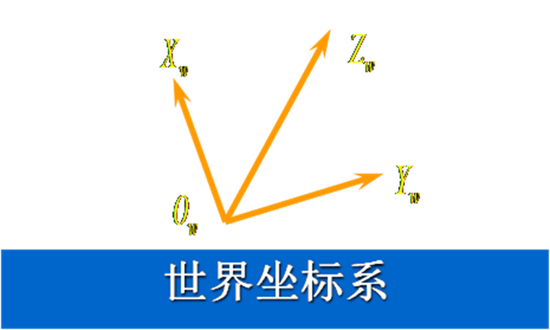
World coordinate system (Xw, Yw, Zw)
It is a user-defined three-dimensional coordinate system used to describe the coordinate positions between objects and cameras in three-dimensional space, following the right-hand rule. The world coordinate system is the true coordinate system that reflects the position of objects in the physical world.
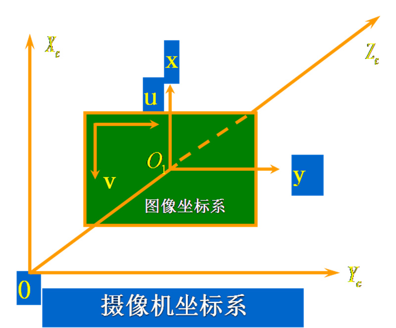
Camera coordinate system (Xc, Yc, Zc)
Using the optical center of the camera as the origin, the Zc axis coincides with the optical axis and is perpendicular to the imaging plane. The photography direction is taken as the positive direction, and the Xc and Yc axes are parallel to the x and y axes of the image's physical coordinate system.
Image coordinate system (u, v) or (x, y)
It is an image coordinate system (u, v) with the upper left corner of the image as the origin, in pixels,
Zhang Zhengyou calibration method
By adding a vector of 1 after a two-dimensional point m=[u, t] on the image, and a vector of 1 after a 3D point M=[X, Y, Z] in the camera coordinate system, in the pinhole model, the relationship between the 3D point M and its image projection m is:
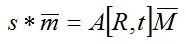
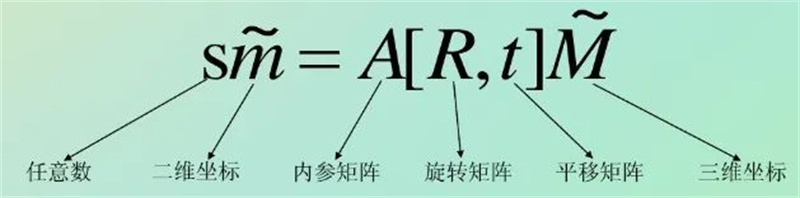
The internal reference A is:

If H=A [R, t] is defined, and s * m=H * M, then H is commonly referred to as a homography matrix. Here, it describes the relationship between a planar 3D point in space and a camera planar 2D point. The coordinate points in the camera plane can be obtained by image processing to find corner points, and the spatial planar 3D point can be obtained through a calibration board with known dimensions. Therefore, a corresponding H matrix can be calculated for each image.
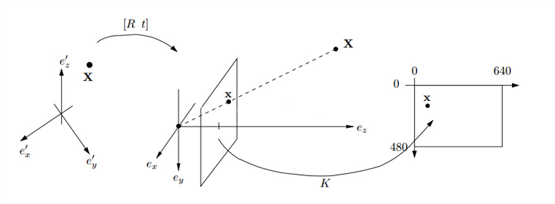
Rotate the calibration template, take n images of the chessboard calibration template from different angles, calculate the inner and outer parameter matrices, and obtain the projection matrix of camera coordinates and image coordinates. This allows for mapping a point in space to a point in the image:
Zhang Zhengyou Camera Calibration Process
1. Print chessboard calibration paper and attach it to a flat surface;
2. Take pictures of the calibration board at various angles by moving the camera or a flat surface, usually taking 20 pictures;
3. Detect feature points in the image;
4. Calculate 5 internal parameters and all external parameters;
5. Solve the radial distortion coefficient first using the least squares method;
6. Optimize all parameters by finding the minimum parameter value;
Zhang Zhengyou's planar calibration method is a method that falls between traditional calibration methods and self calibration methods. It not only avoids the drawbacks of traditional methods such as high equipment requirements and cumbersome operations, but also has higher accuracy than self calibration methods, meeting the calibration requirements of general desktop vision systems (DVS). The disadvantage of this method is that it requires high professionalism in determining the physical coordinates of the dot matrix on the template and matching the points between the image and the template.
Reprinted from:https://blog.csdn.net/dcrmg/article/details/52880508
This article is for academic sharing only. If there is any infringement, please delete it