Camera calibration is a crucial step that cannot be avoided in image measurement and machine vision applications. Through calibration, the parameters of the camera's imaging geometric model, namely the correspondence between points in three-dimensional space and points in two-dimensional images, can be obtained.
This article explores the importance of camera calibration by dissecting the principle, process, and camera distortion of camera imaging, and introduces and analyzes several common camera calibration methods.
01
The principle of camera imaging
Camera imaging is actually an optical imaging process.
We consider the lens of the camera as a convex lens, where light forms an image on a photosensitive element (CCD/CMOS) through the lens. The photosensitive element converts the photoelectric signal into a digital signal, which is then processed into a digital image through digital information processing (DSP) and stored in a storage medium.
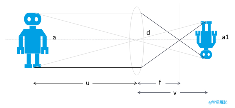
The principle of lens imaging is that the center of a convex lens is the optical center. When light passes through the lens parallel to the main optical axis (dashed line), it converges to the focal point and then refracts to form an image. Among them, robot a represents the physical object, and u represents the object distance; Robot a1 represents imaging and v represents distance; F is the focal length, indicating the distance from the focal point to the optical center.
When the camera's photosensitive element is located near the focal point of the convex lens, and the focal length is infinitely close to the distance from the optical center to the photosensitive element, the camera imaging model becomes familiar to us as "small hole imaging".
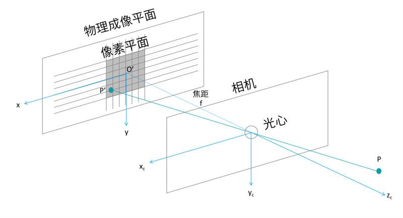
Small hole imaging model
During the camera imaging process, a total of four coordinate systems are involved:
World coordinate system: a user-defined three-dimensional world coordinate system that describes the position of objects and cameras in the real world, with the origin being freely selectable.
Camera coordinate system: With the camera's optical center as the coordinate origin, the x-axis and y-axis are parallel to the x-axis and y-axis of the image coordinate system, and the z-axis is the camera's optical axis.
Image coordinate system: coincides with the imaging plane, with the center of the imaging plane (the intersection of the optical axis and the imaging plane) as the coordinate origin, and the x-axis and y-axis parallel to the two edges of the imaging plane.
Pixel coordinate system: coincides with the imaging plane, with the vertex in the upper left corner of the imaging plane as the origin, and the x-axis and y-axis are parallel to the x-axis and y-axis of the image coordinate system, respectively.
For example, points in the world coordinate system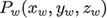 , The coordinates in the camera coordinate system are
  , After projecting to the image coordinate system, the coordinates are
  , The coordinates corresponding to the pixel coordinate system are
  .
.
For ease of calculation, we placed the imaging plane and object on the same side:
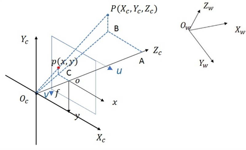
Camera imaging model
02
Using mathematical language to disassemble camera imaging
The camera imaging process can be understood as a cubic transformation between coordinate systems. In an ideal scenario (without considering distortion), the transformation process is shown in the figure:
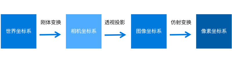
Camera imaging process
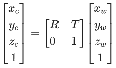
Firstly, the world coordinate system → camera coordinate system
The transformation from the world coordinate system to the camera coordinate system belongs to rigid body transformation, which can be obtained through rotation and translation, where the rotation matrix is R and the translation matrix is T.
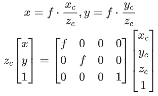
Then, camera coordinate system → image coordinate system
The perspective projection relationship is satisfied from the camera coordinate system to the image coordinate system:
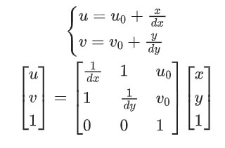
Finally, the image coordinate system → pixel coordinate system
The unit of pixel coordinate system is pixel, where  The coordinates of the center point of the imaging plane in the pixel coordinate system,
 Represent the physical dimensions of each pixel in the x-axis and y-axis directions in the pixel coordinate system.
By synthesizing the formula, we can directly obtain the conversion relationship from the world coordinate system to the pixel coordinate system:
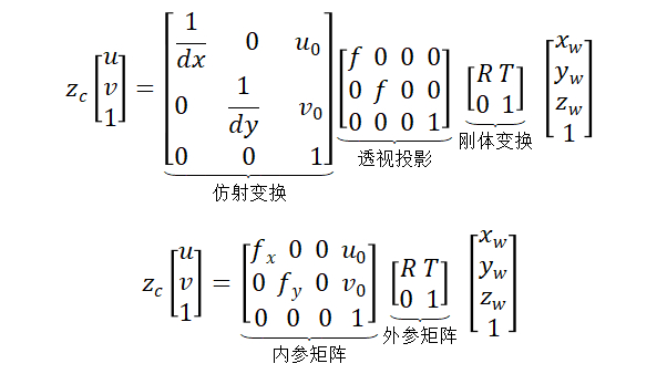
Among them,
The inner parameter matrix depends on the camera's internal parameters, while the outer parameter matrix depends on the position of the camera coordinate system and the world coordinate system. And camera calibration can help us solve for the inner and outer parameter matrices.

03
How to correct camera distortion
Do you think that people who take photos with their phones on a regular basis tend to have distorted faces when they are next to them?

This is actually due to camera distortion. Real lenses may experience distortion during imaging. The distortion caused by the shape of the lens is radial distortion, while the distortion caused by the installation of the lens not parallel to the imaging plane is tangential distortion.
Radial distortion is mainly divided into barrel distortion and pillow distortion.
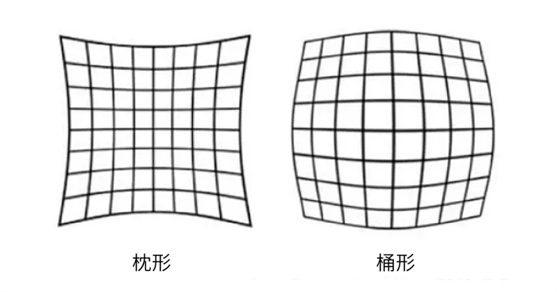
In the small hole imaging model, is a straight line projected onto the pixel plane or a straight line. However, in reality, the lens of a camera often turns a straight line in the real environment into a curve in the image, and the closer it is to the edge of the image, the more pronounced it becomes. Due to the fact that lenses are often centrally symmetrical, irregular distortions are also typically radially symmetrical.
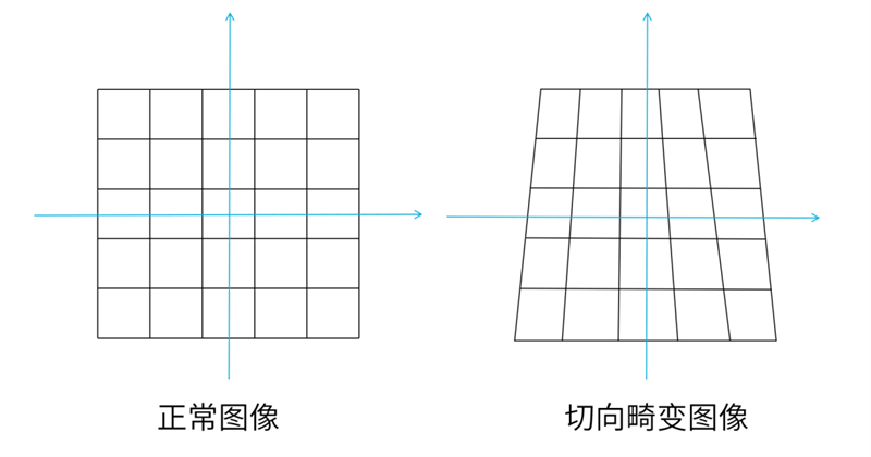
In addition, if there is an error in the installation position of the lens and photosensitive element CCD/CMOS during the camera assembly process, resulting in the lens and imaging plane not being strictly parallel, it will cause tangential distortion.
At this point, when we project a rectangle onto the imaging plane, it is likely to become a trapezoid.
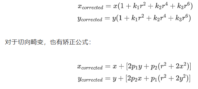
However, these are not significant issues, and there are corresponding formulas to correct them. For radial distortion, the Taylor series expansion can be used, where (x, y) is the actual coordinates after distortion,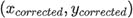 To correct the coordinates, the distance between the point and the imaging center is:
Overall, camera distortion is caused by 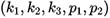 5 parameter descriptions, all of which can be solved using camera calibration. A camera with good quality has negligible tangential distortion, and the radial distortion coefficient k3 can also be ignored. Just calculate the two parameters k1 and k2.
04
Common camera calibration methods
Generally speaking, there are four camera calibration methods: traditional camera calibration, active vision camera calibration, camera self calibration, and zero distortion camera calibration.
Traditional camera calibration method
It is necessary to use a calibration object with known dimensions, establish the correspondence between the points on the calibration object with known coordinates and their image points, and use a certain algorithm to obtain the internal and external parameters of the camera model.
It can be used for any camera model with high accuracy, but calibration always requires calibration objects. Two or more images must be used, and the production accuracy of calibration objects will affect the calibration results. Common methods include Tsai two-step method, Zhang's calibration method, etc.
Active Vision Camera Calibration Method
The camera calibration method based on active vision refers to calibrating the camera with certain motion information known to the camera. By controlling the camera to perform certain specific movements and capturing multiple sets of images, the camera's internal and external parameters are solved based on image information and known displacement changes.
This method does not require calibration objects, has a simple algorithm and high robustness, but its disadvantages are high cost and expensive equipment.

Camera self calibration method
The self calibration algorithm mainly utilizes the constraints of camera motion, has strong flexibility, and can calibrate the camera online.
But it is based on absolute quadratic curves or surfaces, and the algorithm has poor robustness. Due to the strong motion constraints of the camera, it is not practical in practical life. Common methods include hierarchical stepwise calibration and Kruppa equation based calibration.
Zero distortion camera calibration method
It is a mapping relationship established between LCD pixels and camera sensor pixels using an LCD display screen as a reference and a phase-shifting grating as a medium, to determine the viewpoint position of each camera pixel on the LCD.
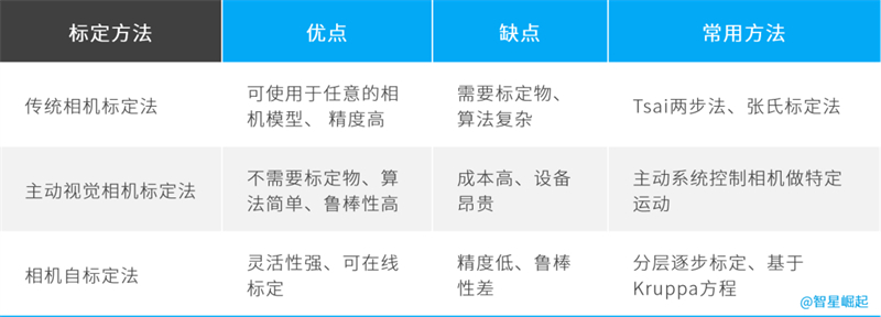
Comparison of Several Common Camera Calibration Methods
These four calibration methods each have their own advantages and disadvantages, and can be selected according to one's own situation. The most commonly used method among them is the Zhang Zhengyou calibration method (Zhang's calibration method), which is simple to operate and has high accuracy, and can meet most occasions.
The Zhang Zhengyou calibration method uses a chessboard calibration board to calibrate and fix the world coordinate system on the chessboard. The size of each grid on the chessboard is known, that is, the coordinates of each corner of the chessboard in the world coordinate system can be calculated.
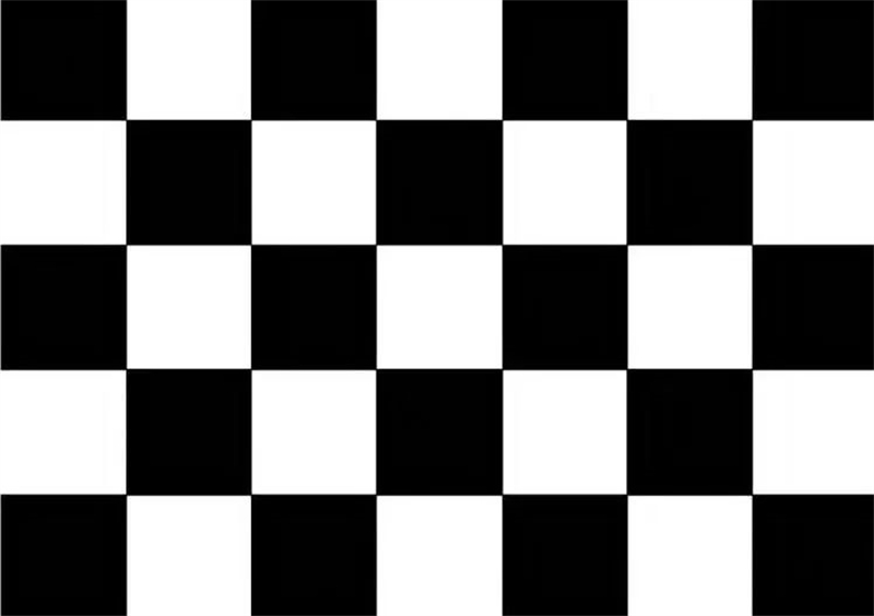
Checkerboard marking grid
When the camera captures an image of the calibration board, the corresponding image detection algorithm can be used to obtain the coordinates of each corner point in the pixel coordinate system, thereby obtaining the camera's inner and outer parameter matrices and distortion parameters. It should be noted that Zhang Zhengyou's calibration method only considers radial distortion and does not consider tangential distortion.
The above is all the sharing for this issue. For more information on how to derive Zhang Zhengyou's calibration method, interested students can click "watching". If the number of views exceeds "50", it will appear in subsequent articles!